Fiat 500 (from 2015) – fuse box diagram (USA diagram)
Year of production: 2015, 2016
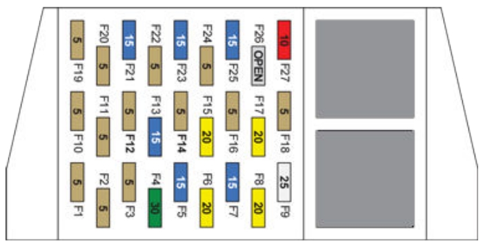
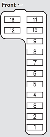
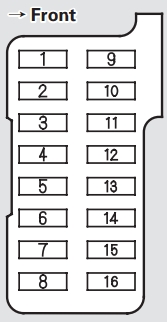
Interior fuses
The interior fuse panel is part of the Body Control Module (BCM) and is located on the drivers’s side under the instrument panel.
| Cavity |
Vegicle fuse number |
Mini fuse (ampere fuse) |
Colour |
Description |
| 1 |
F12 |
7,5 |
Brown |
Right Low Beam |
| 2 |
F32 |
5 |
Tan |
Front and Rear Ceiling Lights Trunk and Door Courtesy Lights |
| 3 |
F53 |
5 |
Tan |
Instrument Panel Node |
| 4 |
F38 |
20 |
Yellow |
Central Door Locking |
| 5 |
F36 |
10 |
Red |
Diagnostic Socket, Car Radio, Climate Control System |
| 6 |
F43 |
20 |
Yellow |
Bi-Directional Washer |
| 7 |
F48 |
20 |
Yellow |
Passenger Power Window |
| 8 |
F13 |
7,5 |
Brown |
Left Low Beam, Headlamp Leveling |
| 9 |
F50 |
7,5 |
Brown |
Airbag |
| 10 |
F51 |
5 |
Tan |
Car Radio Switch, Climate Control System, Stop Light, Clutch |
| 11 |
F37 |
5 |
Tan |
Stop Light Switch, Instrument Panel Node |
| 12 |
F49 |
5 |
Tan |
Exterior Mirror, GPS, Electric Mirror, Parking Sensor |
| 13 |
F47 |
20 |
Yellow |
Driver Power Window |
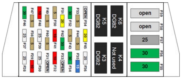
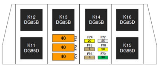
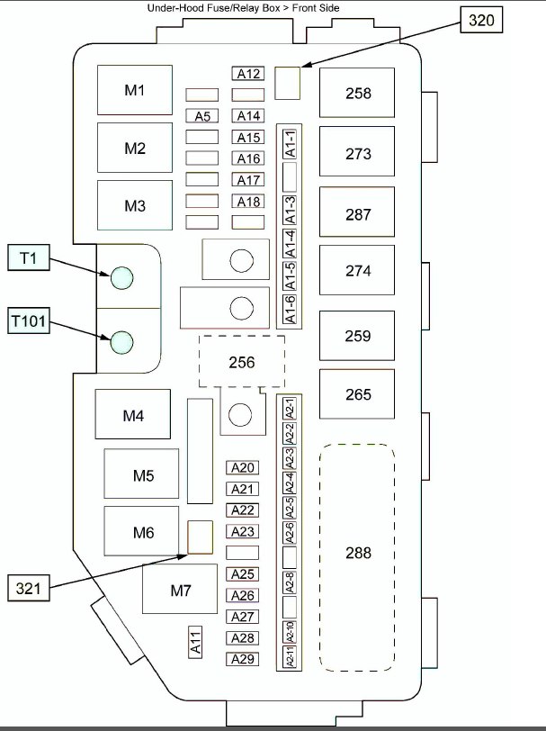
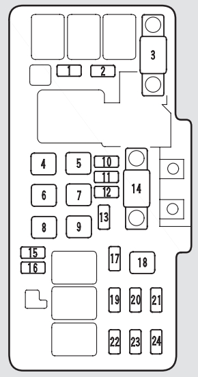
Underhood fuses
The front distribution units is located on the right side of engine compartment, next to the battery.
| Cavity |
Maxi fuse |
Mini fuse |
Description |
| F01 |
60A (Blue) |
— |
Body Controller |
| F02 |
20A (Yellow) |
— |
Audio Amplifier |
| F03 |
20A (Yellow) |
— |
Ignition Switch |
| F04 |
40A (Orange) |
— |
Anti-Lock Brake Pump |
| F05 |
70A (Tan) |
— |
Electric Power Steering |
| F06 |
20 (Yellow) |
— |
Radiator Fan – Single Speed |
| F06 |
30A (Green) |
— |
Radiator Fan – Low Speed |
| F07 |
40A (Orange) |
— |
Radiator Fan – High Speed |
| F08 |
30A (Green) |
— |
Blower Motor |
| F09 |
— |
10A (Red) |
Powertrain |
| F10 |
— |
10A (Red) |
Horn |
| F11 |
— |
15A (Blue) |
Powertrain |
| F11 |
— |
10A (Red) |
Powertrain (Multiair – If Equipped) |
| F14 |
— |
5 (Tan) |
High beam (Shutter) |
| F15 |
— |
15A (Blue) |
Cigar Lighter |
| F16 |
— |
7,5 (Brown) |
Transmission |
| F17 |
— |
25A (White) |
Powertrain (Multiair – If Equipped) |
| F17 |
— |
15A (Blue) |
Powertrain |
| F18 |
— |
15A (Blue) |
Powertrain |
| F18 |
— |
5 (Tan) |
Powertrain (Multiair – If Equipped) |
| F19 |
— |
7,5 (Brown) |
Air Conditioning |
| F20 |
— |
15A (Blue) |
Heated Seats – If Equipped |
| F21 |
— |
15A (Blue) |
Fuel Pump |
| F22 |
— |
20A (Yellow) |
Powertrain |
| F23 |
— |
20A (Yellow) |
Anti-Lock Brake Valves |
| F24 |
— |
7,5A (Brown) |
Stability Control System |
| F30 |
— |
15A (Blue) |
Fog Lamps |
| F82 |
30A (Green) |
— |
Sunroof/ Convertible Top |
| F83 |
20A (Yellow) |
— |
Cooling Pump – If Equipped |
| F84 |
— |
10A (Red) |
Transmission |
| F85 |
30A (Green) |
— |
Rear Defroster |
| F87 |
— |
5A (Tan) |
Rear Defroster |
| F90 |
— |
5A (Tan) |
Heated Mirrors – If Equipped |
The ID number of the electrical component corresponding to each fuse can be found on the back of the cover.
WARNING: Terminal and harness assignments for individual connectors will vary depending on vehicle equipment level, model, and market.