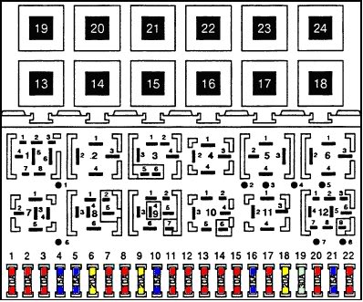
Instrument cluster, battery saver, number plate lamp
Side and tail lamps
Central locking
Hazard warning flashers and direction indicators
Ignition
Brake lamps
Reversing lamp
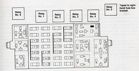
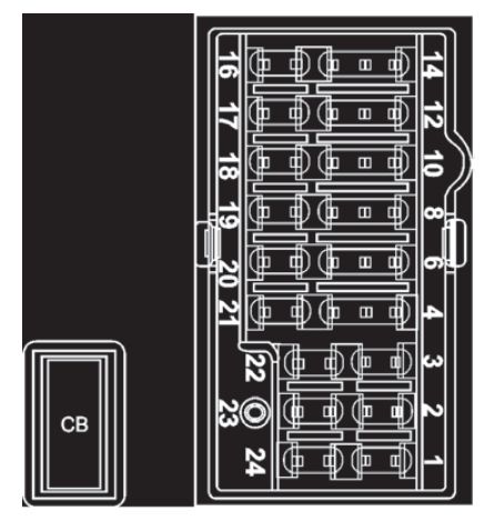
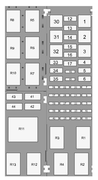
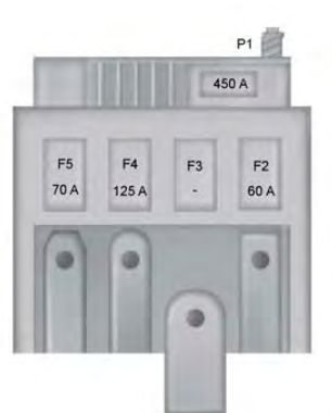
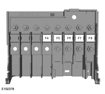
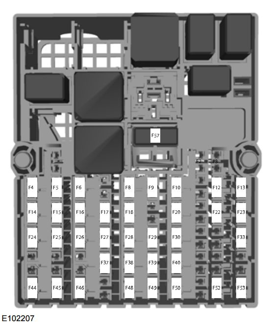
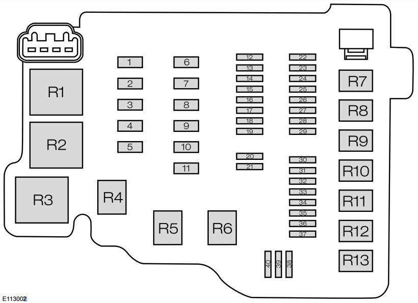
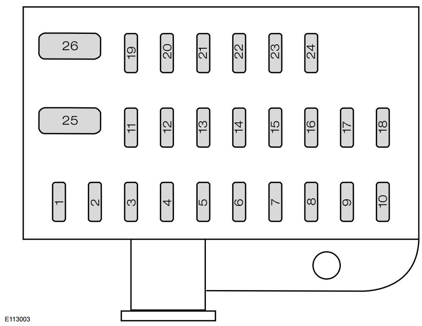
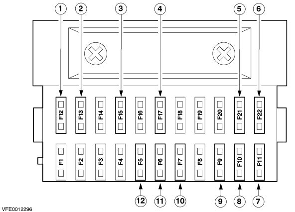
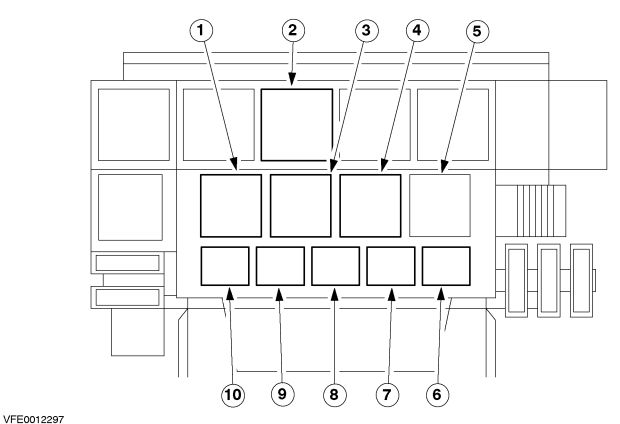
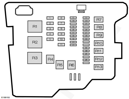
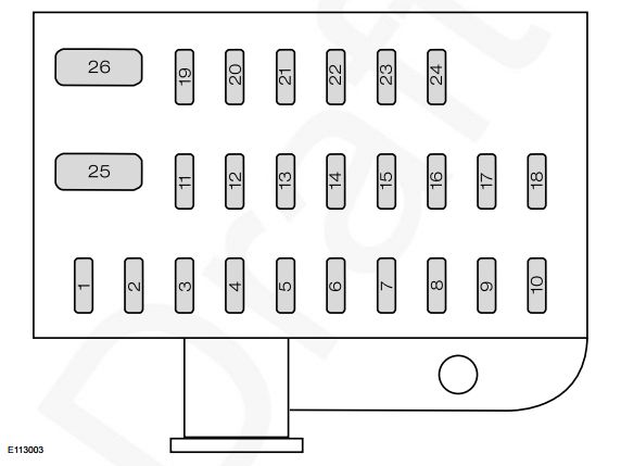
FUSE BOX LOCATIONS (G980155) Central fuse box
The central fuse box is located behind the glove box in the instrument panel.
To get access to the fuse box:
Open the glove box and empty it before continuing.
Press the side parts of the glove box inwards and swivel the box further down.
The fuse chart label located on the rear side of the glove box will help you identify the fuses. Depending on vehicle variant the necessary fuses and relays may vary.
Reinstall in the reverse order.
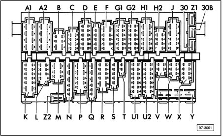
WARNING: Terminal and harness assignments for individual connectors will vary depending on vehicle equipment level, model, and market.
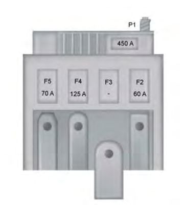
Ford Fusion (2008) – fuse box diagram (India version)
Year of production: 2008
Fuse labels
Labels
Description
See Owner’s handbook
ABS
Headlamp dipped beam
Headlamp main beam
Fog lamps
Lighting control
Windscreen wipers
Rear window wiper
Heated rear window
Electric exterior mirrors
Blower motor
Air conditioning
Cigar lighter
Horn
Engine management (diesel) or catalytic converter
Starter motor
Audio system and diagnostic connector
Engine management or electronic module
Fuel pump
Battery and charging system
Instrument cluster, battery saver, number plate lamp
Side and tail lamps
Central locking
Hazard warning flashers and direction indicators
Ignition
Brake lamps
Reversing lamp
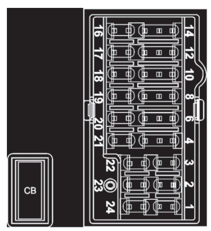
FUSE BOX LOCATIONS (G980155) Central fuse box
The central fuse box is located behind the glove box in the instrument panel.
To get access to the fuse box:
Open the glove box and empty it before continuing.
Press the side parts of the glove box inwards and swivel the box further down.
The fuse chart label located on the rear side of the glove box will help you identify the fuses. Depending on vehicle variant the necessary fuses and relays may vary.
Reinstall in the reverse order.
WARNING: Terminal and harness assignments for individual connectors will vary depending on vehicle equipment level, model, and market.