Ford Endeavour mk3 (Third Generation from 2015) – fuse box diagram (India version)

Ford Endeavour mk3 (Third Generation from 2015) – fuse box diagram (India version)

Year of production: 2015, 2016

Fuse block (Engine compartment)

Ford Endeavour mk2 (Second Generation) - fuse box - engine compartment
Ford Endeavour mk3 (Third Generation) – fuse box – engine compartment
Fuse Description Ampere rating [A] Protected Component
1 MAIN 80 For protection of all circuits
2 GLOW 60 Glow plug
3 IG KEY1 40 Engine control system, Instrument cluster, Lighter, Power Windows
4 BTN2 60 Headlights
5 INJ/FIP 20 Fuel system
6 ABS 40 ABS motor, Hazard, Brake lights
7 PTC/AT 30 AT controller module
8 IG KEY2 60 Air conditioner, Windscreen wiper and washer
9 BTN1 60 Air conditioner, Rear defogger, Door lock, ABS solenoid, Power windows, Room, Tail lights, Fog lights

Central Junction Box (passenger compartment)

Ford Endeavour mk2 (Second Generation) - fuse box - passenger compartment
Ford Endeavour mk3 (Third Generation) – fuse box – passenger compartment
Fuse Description Ampere rating [A] Protected component
1 CIGAR 20 Lighter (IF EQUIPPED), Radio, Remote control mirror, Power out let
2 R.WIP 10 Rear Window wiper and washer
3 WIPER 15 Windscreen wiper and washer
4 A/C2 10 Air conditioner, ABS relay
5 D.LOCK 30 Power door locks
6
7 ABS/SOL 20 ABS solenoid
8 STOP 15 Brake lights, Horn
9 HAZARD 10 Direction indicators
10 METER 15 Instrument cluster, Reverse lights, Direction indicators, (IF EQUIPPED)RFW
11 ENGINE 15 Engine control system
12 P.POINT 15 Power point
13 A/C 10 Magnet clutch (IF EQUIPPED)
14 DEFOG 20 Rear defogger
15 F.OPEN 15 Fuel flap opener
16 HEAD RH 15 Head light (Right)
17 HEAD LH 15 Head light (Left)
18 FOG 15 Fog lights (IF EQUIPPED)
19 TAIL 10 Tail lights, Position lights, Number plate lights
20 ROOM 15 Over head lights, Audio (IF EQUIPPED)
21 R. A/C 20 Air conditioner
22 P.WIND 30 Power windows

WARNING: Terminal and harness assignments for individual connectors will vary depending on vehicle equipment level, model, and market.

Ford Endeavour mk2 (Second Generation 2006 – 2015) – fuse box diagram (India version)

Ford Endeavour mk2 (Second Generation 2006 – 2015) – fuse box diagram (India version)

Year of production: 2006, 2007, 2008, 2009, 2010, 2011, 2012, 2013, 2014, 2015

Fuse block (Engine compartment)

Ford Endeavour mk2 (Second Generation) - fuse box - engine compartment
Ford Endeavour mk2 (Second Generation) – fuse box – engine compartment
Fuse Description Ampere rating [A] Protected Component
1 MAIN 80 For protection of all circuits
2 GLOW 60 Glow plug
3 IG KEY1 40 Engine control system, Power Window, Instrument cluster, Lighter
4 BTN2 60 Head lights
5 INJ/ALT 20 Fuel system
6 ABS 40 ABS motor
7 PTC/AT 30 AT controller module
8 IG KEY2 60 Air conditioner, Windscreen wiper and washer
9 BTN1 60 Air-conditioner, Rear defogger, Door lock, ABS solenoid, Room, Tail lights, Fog lights


Central Junction Box (passenger compartment)

Ford Endeavour mk2 (Second Generation) - fuse box - passenger compartment
Ford Endeavour mk2 (Second Generation) – fuse box – passenger compartment
Fuse Description Ampere rating [A] Protected component
1 CIGAR 20 Lighter, Radio, Remote Control mirror, Power outlet
2 R.WIP 10 Rear Window wiper and washer
3 WIPER 15 Windscreen wiper and washer
4 A/C2 10 Air conditioner
5 D.LOCK 30 Power door locks
6
7 ABS/SOL 20 ABS solenoid
8 STOP 15 Brake lights, Horn
9 HAZARD 10 Direction indicators
10 METER 15 Instrument cluster, Reverse lights, Direction indicators
11 ENGINE 15 Engine control system
12 P.POINT 15 Power point
13 A/C 10 Magnet clutch
14 DEFOG 20 Rear defogger
15 F.OPEN 15 Fuel flap opener
16 HEAD RH 15 Head light (Right)
17 HEAD LH 15 Head light (Left)
18 FOG 15 Front fog lights
19 TAIL 10 Parking lights, Number plate lights
20 ROOM 15 Over head lights, Audio
21 R. A/C 20 Air conditioner
22 P.WIND 30 Power windows

WARNING: Terminal and harness assignments for individual connectors will vary depending on vehicle equipment level, model, and market.

Ford EcoSport mk2 (Second Generation) (from 2013) – fuse box diagram (India version)

Ford EcoSport mk2 (Second Generation) (from 2013) – fuse box diagram (India version)

Year of production: 2013, 2014, 2015, 2016


Engine Compartment Fuse Box

Ford EcoSport (2013) - fuse box - engine compartment (India version)
Ford EcoSport (2013) – fuse box – engine compartment (India version)
Fuse Ampere rating [A] Circuits protected
1 40 Anti-lock braking system, electronic stability program module
2 60 Cooling system fan high speed
3 30 Cooling system fan low speed
4 40 Heater blower relay
5 60 Passenger compartment fuse box supply (battery)
6 30 Power door locks (body control module)
7 60 Passenger compartment fuse box supply (ignition relay)
8 60 Glow plug relay (diesel)
9 30 Automatic transmission module
10 Not used
11 30 Starter relay
12 15 High beam relay
13 Not used
14 Not used
15 Not used
16 15 Cooling fan relay, powertrain control module, canister purge valve (petrol), wastegate valve (1.0L petrol), variable oil pump valve (1.0L petrol), variable camshaft timing valve (1.0L petrol)
17 15 Heated oxygen sensors (petrol), variable camshaft timing (1.5L petrol), catalyst monitoring sensor (1.5L petrol), mass air flow sensor (1.5L petrol and diesel), powertrain control module (diesel), metering fuel valve (diesel), temperature sensor (diesel), vehicle speed sensor (diesel), water in fuel sensor (diesel)
18 (1.0L petrol) 10 Run on pump, vacuum valve
19 (1.0L petrol) 20 Ignition coil
19 (1.5L petrol) 15 Ignition coil
20 Not used
21 15 Horn
22 15 Exterior lighting left-hand side (low beam)
23 15 Fog lamp relay
24 15 Turn signals
25 Not used
26 Not used
27 7,5 Powertrain control module relay coil, automatic transmission module, powertrain control module (1.5L petrol)
28 20 Anti-lock Braking System (electronic stability program)
29 7,5 Air conditioning clutch relay
30 15 Exterior lighting right-hand side (low beam)
31 Not used
32 20 Body control module power supply
33 20 Rear window defroster
34 20 Fuel pump relay (petrol)
35 Not used
36 Not used
37 Not used
38 Not used
39 Not used
40 Not used


Relay Circuits switched
R1 Cooling fan motor – high speed
R2 Not used
R3 Powertrain control module
R4 High beam
R5 Horn
R6 Not used
R7 Cooling fan motor – low speed
R8 Starter motor
R9 Air conditioning
R10 Front fog lamp
R11 Fuel pump (1.5L petrol)
R12 Backup lamp
R13 Heater fan/blower


Passenger Compartment Fuse Box

Ford EcoSport (2013) - fuse box - passenger compartment (India version)
Ford EcoSport (2013) – fuse box – passenger compartment (India version)
Fuse Ampere rating [A] Circuits protected
1 7,5 Passenger Compartment Fuse Box
2 10 Stop lamps
3 7,5 Reversing lamp
4 7,5 Headlamp leveling
5 20 Windshield wipers
6 15 Rear window wiper
7 15 Washer pump
8 Not used
9 Not used
10 15 
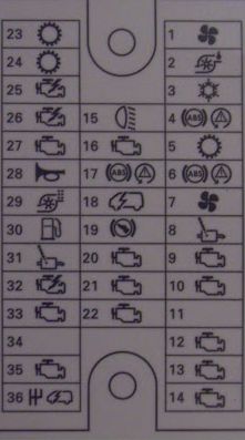
Ignition switch or keyless ignition relay, keyless accessory relay
11 3 Instrument cluster
12 15 Data link connector
13 7,5 Heating control head (manual A/C), electronic automatic temperature control, receiver remote (vehicles with keyless system), integrated control panel, multifunction display
14 15 Audio, SYNC
15 3 Power exterior mirrors, power windows
16 20 Keyless vehicle module
17 20 Keyless vehicle module
18 Not used
19 7,5 Instrument cluster
20 Not used
21 Not used
22 Not used
23 Not used
24 Not used
25 7,5 Air conditioning control module, heater blower relay, front fog lamp relay
26 3 Airbag control module
27 10 Body control module (ignition), anti-lock brake system, ignition (for vehicles without keyless system), cluster (ignition), electrical power assist steering (ignition)
28 7,5 Accelerator pedal, fuel pump, powertrain control module (ignition), automatic transmission module
29 Not used
30 Not used
31 20 Front power point
32 20 Rear power point
33 Not used
34 30 Power driver and passenger window switches
35 30 Power rear window switches
36 Not used


Relay Circuits switched
R1 Iginition
R2 Keyless system ignition
R3 Keyless system accessoty

Battery Fuse Box

Ford Ecosport (2013) - fuse box battery (India version)
Ford Ecosport (2013) – fuse box battery (India version)
Fuse Ampere rating [A] Circuits protected
1 450 Starter
2 60 Electric power assist steering
3 200 Engine junction box
4 Not used
5 Not used
6 3 Battery monitor system

WARNING: Terminal and harness assignments for individual connectors will vary depending on vehicle equipment level, model, and market.

Ford Figo (from 2010) – fuse box diagram (India version)

Ford Figo (from 2010) – fuse box diagram (India version)

Year of production: 2010, 2011, 2012, 2013, 2014, 2015, 2016

Fuse labels

Labels Description
See Owner's handbook See Owner’s handbook
Airbag Airbag
ABS ABS
Dipped beam Headlamp dipped beam
Main beam or headlamps Headlamp main beam
Dipped beam or parking lamp switch Lighting control
Rear window wiper Windscreen wipers
Heated rear window Heated rear window
Air conditioning, heater blower motor Blower motor
Air conditioning Air conditioning
Horn Horn
Engine management, electronic module Engine management or electronic module
Fuel pump Fuel pump
Battery sensing Battery and charging system
Instrument cluster Instrument cluster, battery saver, number plate lamp
Side and tail lamps Side and tail lamps
Central locking and alarm horn Central locking
Hazard warning flashers and direction indicators Hazard warning flashers and direction indicators
Ignition Ignition
Brake lamps Brake lamps
Reversing lamp Reversing lamp

Engine junction box

Ford Figo (2010) - fuse box - engine junction
Ford Figo (2010) – fuse box – engine junction
Fuse Ampere rating [A] Circuits protected
F1 Not used
F2 Not used
F3 60 Diesel glow plug relay
F4 40 Cooling fan and AC (Duratec – Petrol)
50 Cooling fan and AC (Duratorq – Diesel)
F5 60 PJB busbar BB1
F6 60 Ignition Relay
F7 60 PJB busbar BB4
F8 60 PJB busbar BB5

Passenger junction box

Ford Figo (2010) - fuse box - passenger junction
Ford Figo (2010) – fuse box – passenger junction
Fuse Ampere rating [A] Circuits protected
F1 Not used
F2 Not used
F3 Not used
F4 10 Air conditioning clutch
F5 20 ABS valve
F6 7,5 Power mirrors
F7 10 Electric decklid release
F8 Not used
F9 10 Head lamp low (dipped) beam – LHS
F10 10 Head lamp low (dipped) beam – RHS
F11 Not used
F12 15 Powertrain control module fuse
F13 20 Heated oxygen sensor – Petrol
Powertrain control module – Diesel
F14 Not used
F15 20 Fuel pump
F16 3 Powertrain control module power
F17 15 Lighting switch
F18 15 Onboard diagnotics/radio
F19 Not used
F20 7,5 Instrument cluster
F21 Not used
F22 7,5 Park/tail lamp – LHS
F23 7,5 Park/tail lamp – RHS
F24 20 Power door locks (BFC)
F25 15 Turn/hazard lamp
F26 20 Heated back window
F27 15 Horn
F28 3 Alternator
F29 20 Front power outlet connector
F30 15 Ignition switch
F31 7,5 Cargo/dome Lamp
F32 10 Driver door unlock power (BFC)
F33 7,5 License plate lamp
F34 3 Rear window heater switch
F35 Not used
F36 10 Turn/hazard flasher
F37 3 ABS module
F38 7,5 HVAC control panel/Thermistor assy/BFC
F39 7,5 Air bag module
F40 10 Light/dimmer switch
F41 7,5 Instrument cluster
F42 Not used
F43 Not used
F44 3 Radio/Instrument cluster
F45 15 Stop lamps
F46 20 Front wiper
F47 10 Rear wiper park position
F48 7,5 Back up lamp
F49 Not used
F50 20 Fog lamps
F51 Not used
F52 10 High beam – LHS
F53 10 High beam – RHS
F54 Not used
F55 Not used
F56 Not used
F57 30 Front power windows
F58 30 Heated blower motor
F59 30 Starter motor
F60 30 ABS Pump

WARNING: Terminal and harness assignments for individual connectors will vary depending on vehicle equipment level, model, and market.

Smart Fortwo (1998 – 2002) – fuse box diagram

Smart Fortwo (1998 – 2002) – fuse box diagram

Year of production: 1998, 1999, 2000, 2001, 2002

Fuse box in passenger compartment

Smart Fortwo mk1 - fuse box
Smart Fortwo mk1 – fuse box
Fuse Consumer Ampere rating [A] Color
1 Parking and tail lights, r. Terminal 58 f. instrument panel illumination, license plate light 7,5 Brown
2 Parking and tail lights, l. 7,5 Brown
3 Front fog lights 15 Blue
4 Fog tail lights 7,5 Brown
5 Low beam lights, l. with headlight range adjuster 7,5 Brown
6 Low beam lights, r. with headlight range adjuster 7,5 Brown
7 High beam lights, l., high-beam tell-tale 7,5 Brown
8 High beam lights, r. 7,5 Brown
9 Ignition coil, starter B01 25 Nature
Starter, D01 15 Blue
10 Indicator lamp, brake lights 15 Blue
11 Radio, CD-charger, instrument cluster, tachometer, back-up light, seat sensor, diagnosis socket 15 Blue
12 12-Volt power socket 15 Blue
13 Interior illumination, rear diagnosis socket 15 Blue
14 Radio, CD-changer 15 Blue
15 Instrument cluster, remote control receiver, central locking, ant-theft alarm, remote tailgate unlocking switch 7,5 Brown
16 Remote locking actuator motors, safety unit, clock, horn, lower interior light (switch), remote tailgate unlocking 15 Blue
17 Rear-window wiper 15 Blue
18 MCO soft top 25 Nature
19 MCO soft top 25 Nature
20 Engine control unit (petrol only) 7,5 Brown
21 Rear-window heater, engine fan 30 Green
22 Wiring system 40 Orange
23 Heater blower 20 Yellow
24 Window regulator, l & r 30 Green
25 Windscreen wiper, washer pump 20 Yellow
26 ABs, control units: Airbag engine control units, central control unit 7,5 Brown
27 ABS control unit 50 Red

WARNING: Terminal and harness assignments for individual connectors will vary depending on vehicle equipment level, model, and market.

Smart Fortwo (2013) coupe and cabriolet – fuse box diagram (USA version)

Smart Fortwo (2013) coupe and cabriolet – fuse box diagram (USA version)

Year of production: 2013

Fuse box in the passenger compartment

Smart Fortwo mk3 - fuse box
Smart Fortwo mk3 – fuse box
Smart Fortwo mk3 - fuse box - rear side
Smart Fortwo mk3 – fuse box – rear side


Fuse Accessory/component Ampere rating [A] Color
1 Engine 25 Neutral
2 Windshield wipers 25 Neutral
3 Power window (left and right) 20 Yellow
4 Passenger compartment blower (HVAC) 25 Neutral
5 Front fog lamps, LED daytime running lamps 10 Red
6 Right parking lamp, right tail lamp, license plate lamps 7,5 Brown
7 Left parking lamp, left tail lamp 7,5 Brown
8 Engine, transmission, shifter 25 Neutral
9 Engine 7,5 Brown
10 Engine, transmission, shifter 15 Blue
11 ESP® control unit 25 Neutral
12 Exterior lamp switch, turn signal lamp switch, cockpit switch module, on-board diagnostics socket, transmission control unit, exterior rear view mirror heating, anti-theft warning system, rain-light sensor, auxiliary instruments, central locking system, instrument cluster, Tire Pressure Monitoring System (TPMS), brake and turn signal lamps (left and right) 10 Red
13
14 Air conditioning compressor 15 Blue
15 Audio, subwoofer, sound system, soft top (cabriolet only), interior light 15 Blue
16 Fuel pump with fuel level sensor 15 Blue
17 Rear window wiper (coupé only) 15 Blue
18 ESP® control unit, EPS control unit, restraint system 10 Red
19 Engine control unit, transmission control unit, Tire Pressure Monitoring System (TPMS), on-board diagnostics socket 7,5 Brown
20 Air conditioning system, exterior rear view mirror adjustment, washer pump, audio, seat heating, wiper switch, soft top switch (cabriolet only) 10 Red
21 Auxiliary power outlet 15 Blue
22 Left low‑beam headlamp 7,5 Brown
23 Right low‑beam headlamp 7,5 Brown
24 Backup lamp 15 Blue
25 Right high‑beam headlamp 7,5 Brown
26 Left high‑beam headlamp 7,5 Brown
27 Engine 7,5 Brown
28 Rear window defroster, radiator cooling fan 40 Orange
29 Soft top (cabriolet only) 30 Green
30 Transmission control unit 40 Orange
31 Horn, central locking system 20 Yellow
32
33 Starter switch (ignition) 50 Red
34 ESP® control unit 40 Orange
35 EPS control unit 30 Green
R1 Exterior rear view mirror heating 7,5 Brown
R2 Brake lamps 7,5 Brown
R3
R4
R5 Windshield unit car2go 10 Red
R6
R7 Interior lighting 5 Light brown
R8 Surround sound system 20 Yellow
R9 Seat heating control unit 25 Neutral

WARNING: Terminal and harness assignments for individual connectors will vary depending on vehicle equipment level, model, and market.

Volkswagen Transporter T5 ESSENTIALS (from September 2009 – 2014) – fuse box diagram

VW Transporter T5 ESSENTIALS (from September 2009 – 2014)  – fuse box diagram

Year of production: 2009, 2010, 2011, 2012, 2013, 2014

Fuse box location

Volkswagen Transporter T5 ESSENTIALS - fuse box location
Volkswagen Transporter T5 ESSENTIALS – fuse box location
Fuse box Location
1 – Fuse holder D – SD In right engine compartment
2 – Fuse holder B – SB In center dash panel
3 – Fuse holder F – SF Under left seat box
4 – Fuse holder C – SC in center dash panel
5 – Fuse holder A – SA In left engine compartment


Fuse holder F (on left in seat box)

Volkswagen Transporter T5 ESSENTIALS - fuse box - holder F
Volkswagen Transporter T5 ESSENTIALS – fuse box – holder F
Fuse Ampere rating [A] Description
SF1 15
SF2 3
SF3 15
SF4 15
SF5 5
SF6 25
SF7 30

12 V socket

SF8 25

Heater control unit, remote control receiver for auxiliary heating

SF9 25

Fresh air blower isolation relay, Voice amplification control unit Rear blower regulation motor

SF10 3

Auxiliary heater relay

15
SF11 15 Cigarette lighter
SF12 15
SF13

Vacant

SF14

Vacant

SF15

Vacant

SF16

Vacant

SF17

Vacant

SF18

Vacant

SF19

Vacant

SF20

Vacant

SF21

Vacant

SF22 15 12V Socket 2
SF23 15 12V Socket 3
SF24 10

only models with auxiliary coolant heater

15
SF25 10

Trailer detector control unit -J345-30

SF26 20

Trailer detector control unit -J345-30

SF27 20

Trailer detector control unit -J345-30

SF28 7,5

Reversing camera system control unit -J772-30a

SF29 Vacant
SF30 5

Voice amplification control unit -J656-30

SF31 Vacant
SF32 Vacant
SF33 15

Driver seat lumbar support adjustment 30 switch

SF34 40

Right sliding door control unit -J731-

SF35 80

Battery isolation relay -J7-30

SF36 40

17-pin connector


Fuse holder D in electronics box in engine compartment

Volkswagen Transporter T5 ESSENTIALS - fuse box - holder D
Volkswagen Transporter T5 ESSENTIALS – fuse box – holder D
Fuse Ampere rating [A] Description
1 5

Radiator fan control unit -J293-87

2 5

Additional coolant pump relay -J496-30

3 5

Heater element for crankcase breather -N79-15

4 Vacant
5 15

Mechatronic unit for dual clutch gearbox -30 J743- Selector lever lock solenoid -N110- Selector lever

6 30

ABS control unit -J104-30

7 Vacant
8 Vacant
9 5

Engine control unit -J623-30

10 5

Secondary air pump relay -J299-

15

Charge pressure control solenoid valve -N75- – Activated charcoal filter system solenoid – valve 1 -N80- -Exhaust gas recirculation cooler change-over valve -N345- Charge pressure control solenoid valve 2 -N274-

11 30

Headlight main beam relay -J12—

12 10

Fuel metering valve -N290- 15 -Fuel pressure regulating valve -N276-or 87

13 10

Left gas discharge light control unit -J343-15

14 5

Fuel pump relay -J17- 15- Relay for supplementary fuel pump -J832- -Clutch pedal switch -F36-

15 10

Reversing light switch -F4-15

16 5

Air mass meter -G70- 15 Brake light switch -F-17-

17 5

TCS and ESP button -E256- 15-ABS control unit -J104-

18 5

Power steering control unit -J500—

19 5

Clutch pedal switch -F36- 15-Air mass meter -G70-1)

20 5

Engine control unit -J623-15

21 5

Exhaust gas recirculation valve -N18-87

22 10

Injector, cylinder 1 -N30- 87a- Injector, cylinder 2 -N31- – Injector, cylinder 3 -N32- -Injector, cylinder 4 -N33-

23 10

Right gas discharge light control unit -J344-15

24 5

Mechatronic unit for dual clutch gearbox -15 J743- Selector lever -E313-

25 30

Engine control unit -J623- 87-Ignition transformer -N152-

26 5

Left day driving light bulb -L174-87

27 10

Continued coolant circulation pump -V51-87

28 15

Treble tone horn -H2-4) 30

29 5

Right day driving light bulb -L175-87

30 20

Fuel system pressurisation pump -G6- 30 – Fuel pump relay -J17- -Relay for supplementary fuel pump -J832-

31 15

Lambda probe heater -Z19- Lambda probe 1 heater after catalytic converter -Z29-2)

32 30

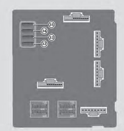
3) -Engine control unit -J623- 5 AElectric fuel pump 2 relay -J49-2)

33 5

Additional coolant pump relay -J496-87

34 5

Onboard supply control unit -J519- (T73b/59)30

35 Vacant87
36 30

Additional coolant pump relay -J496-30

Note:
1) for engine codes CAAA, CAAB, CAAC, CCHA only
2) for engine code AXA only
3) only models with diesel engine
4) for models with taxi equipment only.

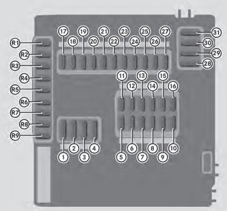
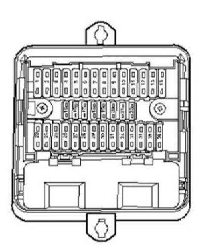
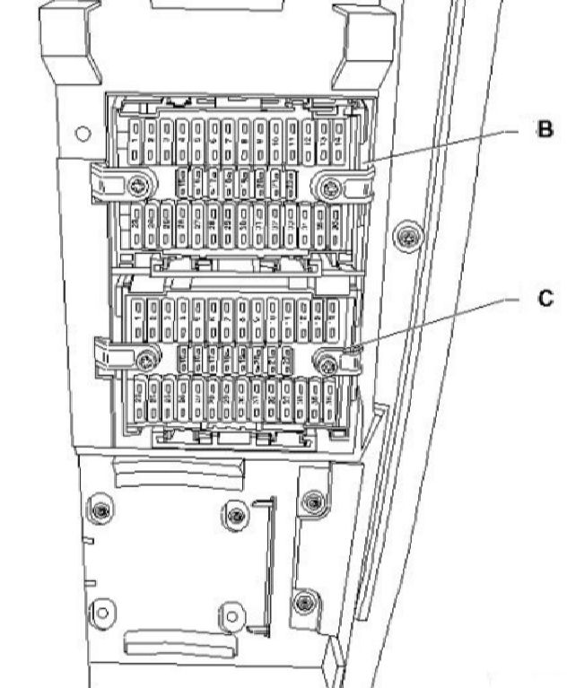
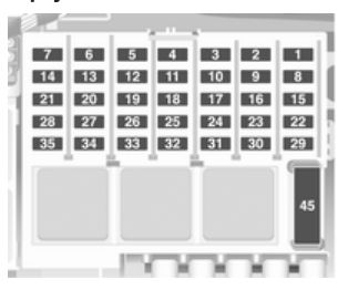
Fuse holder B and C – in the lower fuse box on centre of dash panel

Volkswagen Transporter T5 ESSENTIALS - fuse box - holder B and C
Volkswagen Transporter T5 ESSENTIALS – fuse box – holder B and C

Fuse holder B

Fuse Ampere rating [A] Description
1 30

Terminal 15 voltage supply relay -J329-30

2 5

Steering angle sender -G85-30

3 10

Onboard supply control unit -J519- 30 (T73b/39)

4 5

W8 Connection (15a), in rear wiring harness 15a- Lane change assist control unit 2 -J770- – Lane change assist control unit -J769-

5 15

Left headlight twin filament bulb -L1-56b

6 15

Left headlight twin filament bulb -L1-56a-

7 15

Onboard supply control unit -J519- (T73a/66) 1)

8 15

Rear lid control unit -J605-30 -20 A- Alarm horn -H12- 30- Onboard supply control unit -J519- (T73/16) – Left sliding door control unit -J558- – Rear lid control unit -J605- -Right sliding door control unit -J731-

9 30

Onboard supply control unit -J519-30

10 10

Intermittent wiper switch -E22- 15- Rear wiper switch -E34- -Intermittent wiper regulator -E38-

11 5

Number plate light -X-58

12 5

Light switch -E1-30 30 A

13 7,5

Airbag control unit -J234-15

14 25

Steering column electronics control unit -30 J527-

15 7,5

Fresh air blower switch -E9-75

16 5

Onboard supply control unit -J519- 15 (T73a/44)

17 5

Rear fog light warning lamp -K13- RFL-Rear left fog light bulb -L46-

18 5

Control unit in dash panel insert -J285-30

19 5

Ignition/starter switch -D-86s

20 5

Diagnostic connection -U31-30

21 10

Starter motor relay -J53- 50-Engine control unit -J623-

22 7,5

Control unit in dash panel insert -J285- 15-Diagnostic connection -U31- (T16/1)

23 30

Ignition/starter switch -D- 50 5 A-Onboard supply control unit -J519- (T73b/50)

24 5

Steering angle sender -G85-15

25 7,5

Fresh air blower switch -E9-30

26 30

Light switch -E1-75x

27 15

Right headlight twin filament bulb -L2- 56b- B456 Connection (56b), in main wiring –harness

28 15

Right headlight twin filament bulb -L2- 56a- B142 Positive connection 2 (56a), in interior – wiring harness -Control unit in dash panel insert -J285- (T32/14)

29 10

Dual signal inverter relay -J741-30a

30 10

Left washer jet heater element -Z20- 75- Right washer jet heater element -Z21- – Rear window wiper motor -V12- – Rear right wing door window wiper motor –V93- Rear left wing door window wiper motor -V92-

31 30

Onboard supply control unit -J519- 30 (T73a/73)

32 30

Onboard supply control unit -J519- 30 (T73a/68 )

33 30

Radio -R- 30 Control unit with display for radio and navigation system -J503-

34 25

X-contact relief relay -J59- 15- Fuse 14 on fuse holder D -SD14- -Fuse 20 on fuse holder D -SD20-

35 5

B340 Connection 1 (58d), in main wiring 58d- harness -B341 Connection 2 (58d), in main wiring harness B342 Connection 3 (58d), in main wiring harness

36 25

Onboard supply control unit -J519- 30 (T73b/13)

Note:

1) for models with roof console only

Fuse holder C

Fuse Ampere rating [A] Description
1 15 Trailer detector control unit -J345- 15a -10-pin connector -T10bh/1-75a
2 5 Interior monitor send and receive module 2 -30-G305- Anti-theft and tilt system control unit -J529-
3 101 Red Cross light switch -E10- 30 15 A-Red Cross light warning lamp -K100-
4 10 Differential lock control unit -J187- 15a- Rear differential lock switch -E121- -Four-wheel drive control unit -J492
5 5 SC5-10A-6-pin connector -T6bn/5-75x
6 5 Oil level and oil temperature sender -G266-15
7 30 Rotating light switch -E162- 30 10 A
8 5 Parking aid control unit -J446-30
9 5 Steering column electronics control unit -30 J527- Adaptive cruise control unit -J428-
10 10 Left headlight range control motor -V48- 15 5 A-Right headlight range control motor -V49- Switches and instruments illumination regulator -E20
11 15 Left sliding door control unit -J558-58
12 5 Left day driving light bulb -L174-30 30
13 5 Drive train CAN bus isolation relay -J788-15
14 5 Right day driving light bulb -L175–30A
15 5 Mobile telephone operating electronics 15-control unit -J412-
16 7,5 Navigation system tuner for TV -J415- 30-Interface for external multimedia unit -R215-
17 7,5 Onboard supply control unit -J519- (T73/66) 30 1) -1) 30G 2) Interior lights and compartment lights 2)
18 5 Air conditioning system control unit -J301- 30- Rear fresh air blower switch -E179- – Operating and display unit for rear -Climatronic -E265- Rear blower regulation sender -G463-
19 5 Automatic anti-dazzle interior mirror -Y7- 86s
20 10 Onboard supply control unit -J519- 30 (T73a/64)
21 5 Rain sensor -G213-RPL
22 5 Air conditioning system pressure switch -15-F129- Air quality sensor -G238-
23 10 Residual heat relay -J708- 30a- Remote control receiver for auxiliary coolant -heater -R149- Auxiliary heater operating and display unit -E407- Operating and display unit for camping equipment -E153-
24 7,5 Left centre reading light -W39- 30G- Right centre reading light -W40- – Rear left reading light -W11- – Rear right reading light -W12- – Left interior light -W16– Right interior light -W17- – Rear left interior light -W47- -Rear right interior light -W48-
25 25 Seat heating control unit with regulator -J396-
26 10 Tachograph -G24-30
27 30 D51 Positive connection 1 (15), in engine 15 compartment wiring harness – Fuse 13 on fuse holder D -SD13- -Fuse 23 on fuse holder D -SD23-
28 5

Mirror adjustment switch -E43- 15-Exterior mirror heater button -E231-

29 25

Heater control unit -J162-30

30 5

Operating and display unit for camping 75-equipment -E153- Auxiliary coolant heater relay -J493-

31 25

Sliding sunroof adjustment control unit -30 5 AJ245-

32 20

Headlight washer system relay -J39-15

33 5

Tachograph -G24-15

34 5 Vacant15
35 20

Onboard supply control unit -J519- 30 (T73b/11)

36 5

10-pin connector -T10bh/9-30

Note:
1) for models without roof console only
2) for models with roof console only.

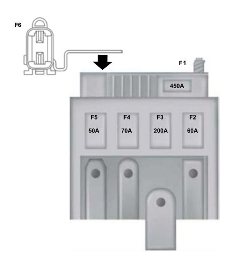
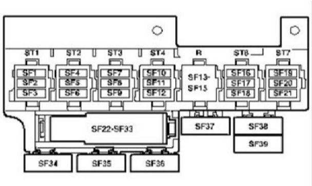
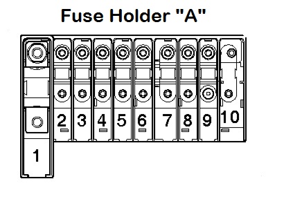
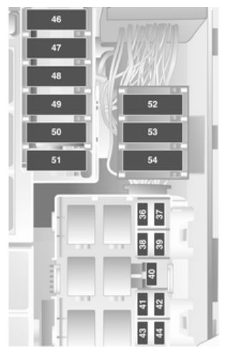
Fuse holder A – in engine bay

Volkswagen Transporter T5 ESSENTIALS - fuse box - holder A
Volkswagen Transporter T5 ESSENTIALS – fuse box – holder A
Fuse Ampere rating [A] Description
1 175

Alternator -C-30 225 A-

2 125

X-contact relief relay -J59- 30- B298 Positive connection 2 (30), in – main wiring harness -B301 Positive connection 5 (30), in main wiring harness B302 Positive connection 6 (30), in main wiring harness B303 Positive connection 7 (30), in main wiring harness B304 Positive connection 8 (30), in main wiring harness B305 Positive connection 9 (30), in main wiring harness Fuse 9 on fuse holder B -SB9- Fuse 14 on fuse holder B -SB14-

3 50

Battery isolation relay -J7- 30 100 A- Second battery charging circuit relay -J713- B310 Positive connection 14 (30), in main wiring harness B311 Positive connection 15 (30), in main wiring harness

4 70

D50 Positive connection (30), in engine 30 compartment wiring harness

5 50

ABS control unit fuse 1 -S123- 30-Fuse 6 on fuse holder D -SD6-

6 60

Automatic glow period control unit -30 50 A-J179- Secondary air pump relay -J299-

7 100

Radiator fan control unit -J293-30

8 40

adiator fan control unit -J293-30 8 – Fuse -40 A – B169 Positive connection 1 (30), in 30 50 A interior wiring harness 100 A- B170 Positive connection 2 (30), in interior wiring harness – Fuse 9 on fuse holder F -SF9- – Fuse 14 on fuse holder F -SF14- – Fuse 22 on fuse holder F -SF22- – Fuse 23 on fuse holder F -SF23- -Fuse 24 on fuse holder F -SF24-

9 100

B272 Positive connection (30), in main 30- wiring harness B299 Positive connection 3 (30), in main wiring harness


WARNING: Terminal and harness assignments for individual connectors will vary depending on vehicle equipment level, model, and market.

Volkswagen Transporter T5 (2003 – 2014) – fuse box diagram

VW Transporter  T5 – fuse box diagram

Year of production: 2003, 2004, 2005, 2006, 2007, 2008, 2009, 2010, 2011, 2012, 2013, 2014

1st raw basic

Volkswagen Transporter T5 - fuse box - Basic option
Volkswagen Transporter T5 – fuse box – Basic option
Fuse Ampere rating [A] Description
1 25 Heater A/C
30
2 5 Steering position sensor
3 10 Multifunction control module1
4 10 Headlamp adjustment
5 15 Headlamp
6 15 Headlamp
7 15 Multifunction control module1 (interior lamp)
8 5 Data link connector (DLC)
9 15 Brake pedal position
10 10 Windscreen wipers (rear)
11 5 Licence plate lamp
12 15 Cigarette lighter
13 5 SRS control module
14 30 Auxiliary heather, heather / A/C
15 7,5 Air conditioning
16 5 Multifunction control module 1
17 5 Rear fog lamps
18 5 Instrumentation control module
19 5 Audio unit, Instrumentation control module1, navigation system
20 5 Side lamp left, LH Stop lamp, LH Tail lamp
21 5 Side lamp left, RH Stop lamp, RH Tail lamp
22 10 Airbag assembly deactivation warning lamp, (DLC), Instrumentation control module
23 25 Starter motor
40 Starter motor (some models with M/T)
24 5 Steering position sensor
25 5 Air conditioning
26 30 Headlamp switch
27 15 Headlamp Right
28 15 Headlamp high beam warning lamp, Headlight Right
29 10 Load area door signal relay
30 10 Heated windscreen washer jets, rear screen wiper motor
31 30 Multifunction control module 1 (Horn)
32 25 Multifunction control module 1 (windscreen wiper motor)
33 15 Audio unit, Navigation system, Traffic information control module
34 25 Automatic transmission, Fuse box/relay plate engine bay 1 (F3, F12, F14-F17, F19, F20, F24)
35 5 Instrument illumination
36 25 Multifunction control module1 (Indicators)

Second raw Options

Volkswagen Transporter T5 - fuse box - second raw option
Volkswagen Transporter T5 – fuse box – second raw option

At the engine bay close to the battery  (remove the battery cover)

Volkswagen Transporter T5 - fuse box at the engine bay
Volkswagen Transporter T5 – fuse box at the engine bay

Under the passenger seat

Fuse Ampere rating [A] Circuit
F1 15 Auxiliary power socket(s) (some models)
F2 15 Auxiliary power socket(s) (some models)
F3 15 Auxiliary power socket(s) (some models)
F4 15 Refrigerator box (camper van), special vehicle equipment
F5 5 Aerial module
F6 25 Auxiliary heater
F7 30 Heater/AC blower motor (ATC)
F8
F9
F10
F11 40 Door function control module, right rear (some models)
F12 80 Auxiliary battery (some models)
Split charge relay (some models)


Location Component
1
2 Split charge relay (with auxiliary battery)
3 Special vehicle equipment
4 Special vehicle equipment
5 Special vehicle equipment

NOTE: Fuses F1-F7/F11/F12 – During assembly these fuses may be fitted in alternative positions, depending on vehicle specification.


WARNING: Terminal and harness assignments for individual connectors will vary depending on vehicle equipment level, model, and market.

Mitsubishi Galant Eighth generation (8th generation) – fuse box diagram

Mitsubishi Galant Eighth generation (8th generation) – fuse box diagram


Fuse box in passenger compartment

Mitsubishi Galant 8th Generation - fuse box - passeneger compartment
Mitsubishi Galant 8th Generation – fuse box – passeneger compartment
Fuse Ampere rating [A] Descritpion
1 15 Stoplights
2 10 Turn signals
3 10 Backup lights
4 30 Heater
5 15 Wiper
6 10 Metters
7 30 Rear window defogger
8 20 {Sundroof}
9 10 4 A/T
10 15 Cigarette lighter
11 10 Heater relay
12 10 Horn
13 Spare fuse


{ } – if so equipped

A/T – Automatic transaxle


Fuse box in engine compartment

Mitsubishi Galant 8th Generation - fuse box - engine compartment
Mitsubishi Galant 8th Generation – fuse box – engine compartment
Fuse Ampere rating [A] Description
Fusible links
1 30 Ignition switch
2 50 {ABS}
3 40 Radiator fan
4 40 Headlights
5 30 Power window
Fuse
6 30 {ABS}
7 30 Condenser fan
8 10 Hazard
9 20 Engine
10 10 {Air conditioning}
11 10 High beam
12 10 Tail lights
13 10 {Theft}
14 15 Fog lights

{ } – if so equipped

WARNING: Terminal and harness assignments for individual connectors will vary depending on vehicle equipment level, model, and market.

Opel Combo C (2001 – 2011) – fuse box diagram

Opel Combo C (2001 – 2011) – fuse box diagram

Years of production: 2001, 2002, 2003, 2004, 2005, 2006, 2007, 2008, 2009, 2010, 2011

Engine compartment fuse box

Fuse boxes of vehicles with engine Z13DTJ

Opel Combo D - bezpiecznik - silnik Z13DTJ
Opel Combo D – fuse box – engine Z13DTJ
Opel Combo D - bezpieczniki - silniki Z13DTJ
Opel Combo D – fuse box – engine Z13DTJ


Fuse Circuit
1 Central control unit
2 Engine control unit
3 Instruments, information display, light switch, horn, hazard warning lamps, immobiliser
4 Towing equipment, number plate lights
5 Power window (left)
6
7
8 Starter
9 Fuel injection system, fuel pump, stationary heater
10 Horn
11 Central control unit
12 Information display, infotainment system
13 Anti-theft alarm system
14 Exterior mirrors
15 Windscreen washer system
16 Courtesy light
17 Central control unit
18
19 Power window (right)
20
21
22 Central control unit, immobiliser
23 Windscreen wipers
24 Infotainment system, information display, light switch, courtesy lamp, instruments, EPS
25 Reversing lights, cigarette lighter, power outlet
26 Seat heater (right)
27 Seat heater (left)
28 ABS
29 Rear window wiper
30 Engine control unit
31 Air conditioning system
32 ABS, manual transmission automated, airbag
33 Engine control
34 Diesel filter heater
35 Power windows, Infotainment system
36 Low beam (left)
37 Low beam (right)
38 Left tail light, left parking light
39 Right tail light, right parking light
40 Brake light
41 Fog light
42 Rear fog light
43 High beam (left)
44 High beam (right)
45 Ventilation fan
46 Engine control unit
47 Heated rear window
48 Starter
49 EPS
50 ABS
51 Petrol engine: manual transmission automated Diesel engine: engine control unit
52 Radiator fan
53 Cooling fan, air conditioning system
54 Manual transmission automated


Fuse boxes of vehicles with other engines

Opel Combo D - bezpieczniki (pozostałe silniki)
Opel Combo D – fuse box  (vehicles other engines)
Opel Combo D - bezpieczniki (pozostałe silniki)
Opel Combo D – fuse box  (vehicles with other engines)
Fuse Circuit
1 Central control unit
2 Engine control unit
3 Instruments, information display, light switch, horn, hazard warning lamps, immobiliser
4 Towing equipment, number plate lights
5 Power window (left)
6
7
8 Starter
9 Fuel injection system, fuel pump, stationary heater
10 Horn
11 Central control unit
12 Information display, infotainment system
13 Anti-theft alarm system
14 Exterior mirrors
15 Windscreen washer system
16 Courtesy light
17 Central control unit
18
19 Power window (right)
20
21
22 Central control unit, immobiliser
23 Windscreen wipers
24 Infotainment system, information display, light switch, courtesy lamp, instruments, EPS
25 Reversing lights, cigarette lighter, power outlet
26 Seat heater (right)
27 Seat heater (left)
28 ABS
29 Rear window wiper
30 Engine control unit
31 Air conditioning system
32 ABS, manual transmission automated, airbag
33 Engine control
34 Diesel filter heater
35 Power windows, Infotainment system
36 Low beam (left)
37 Low beam (right)
38 Left tail light, left parking light
39 Right tail light, right parking light
40 Brake light
41 Fog light
42 Rear fog light
43 High beam (left)
44 High beam (right)
45 Ventilation fan
46 Engine control unit
47 Heated rear window
48 Starter
49 EPS
50 ABS
51 Petrol engine: manual transmission automated Diesel engine: engine control unit
52 Radiator fan
53 Cooling fan, air conditioning system
54 Manual transmission automated

WARNING: Terminal and harness assignments for individual connectors will vary depending on vehicle equipment level, model, and market.