Mercury Sable 4th (Fourth) Generation (2000 – 2005) – fuse box diagram
Year of production: 2000, 2001, 2002, 2003, 2004, 2005
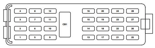
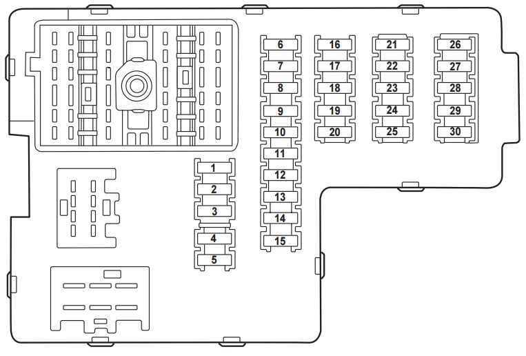
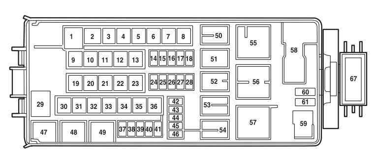
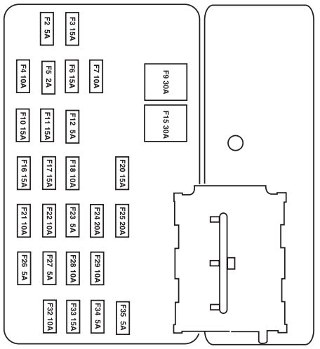
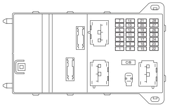
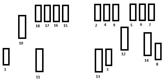
Passenger compartment fuse panel
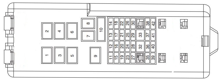
The fuse panel is located below and to the left of the steering wheel by the brake pedal. Remove the panel cover to access the fuses.
| Fuse/relay | Ampere rating [A] | description |
| 1 | — | Accessory delay relay |
| 2 | — | Driver one touch down relay |
| 3 | — | Blower motor relay |
| 4 | — | Flasher relay |
| 5 | — | Not used |
| 6 | — | Not used |
| 7 | 40 | Rear defrost grid feed |
| 8 | 40 | Blower motor |
| 9 | — | Rear defrost relay |
| 10 | 30 | Circuit breaker: Power seats, Delayed accessory, Adjustable pedals |
| 11 | 15 | Integrated control panel (ICP), Rear washer wiper control, Front washer, Cell phone, Passenger switch illumination, GEM, Rear wiper motor |
| 12 | 10 | Heated mirrors, Rear defrost switch |
| 13 | 20 | Power point |
| 14 | — | Not used |
| 15 | 30 | Front wiper motor |
| 16 | 15 | Flasher and GEM power, Integrated control Panel (ICP) power, RCC memory, Cluster |
| 17 | 15 | Stop Lamp, Speed control deactivating switch |
| 18 | — | Not used |
| 19 | — | Not used |
| 20 | — | Not used |
| 21 | — | Not used |
| 22 | 20 | Deck lid release solenoid, lock/unlock relays |
| 23 | 10 | Air bag module, PATS transceiver |
| 24 | 15 | Foglamps and rear foglamps, Transit relay |
| 25 | 2 | PCM relay, Fuel pump relay |
| 26 | 10 | Mirrors, Power antenna, Pulse stretcher Module, Deck lid lamp, Battery saver |
| 27 | 10 | Gauges and warning lamps, Integrated control panel (ICP), FFV sender, GEM |
| 28 | 10 | Blower motor relay coil, EATC logic, Puddle lamps |
| 29 | 15 | Autolamps relay, Fog lamp relay, Fog lamp relay coil, Park lamps, PWM headlamp switch |
| 30 | 15 | Horns and horn switch, OBD II connector |
| 31 | — | Not used |
| 32 | 10 | ABS, DRL relay coil, Speed control actuator, Traction control switch, AC heater selector switch, Blend door actuator, Brake shift interlock, Rear defroster relay coil |
| 33 | — | Not used |
| 34 | — | Not used |
| 35 | — | Not used |
| 36 | 15 | Turn signals, Back-up lamps |
| 37 | 15 | Transmission position switch |
| 38 | 5 | GEM park neutral switch |
| 39 | — | Not used |
| 40 | — | Not used |
| 41 | — | Not used |
| 42 | — | Not used |
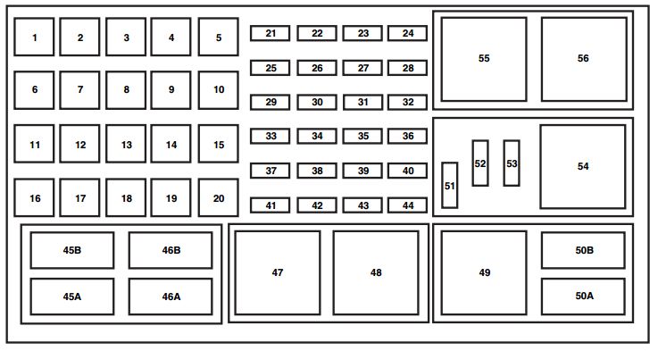
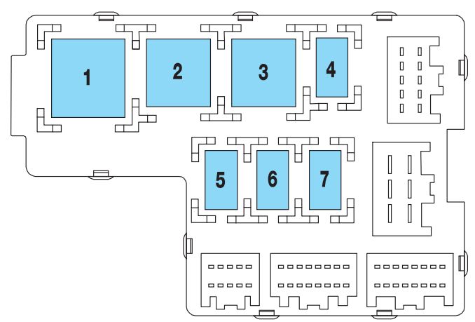
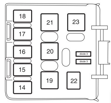
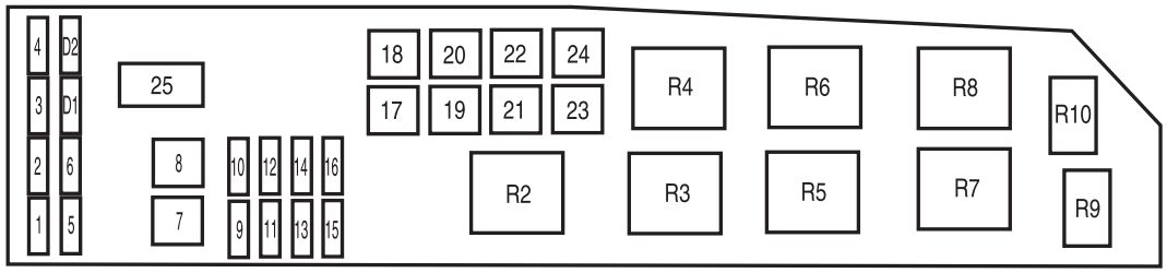
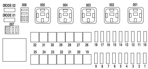
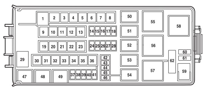
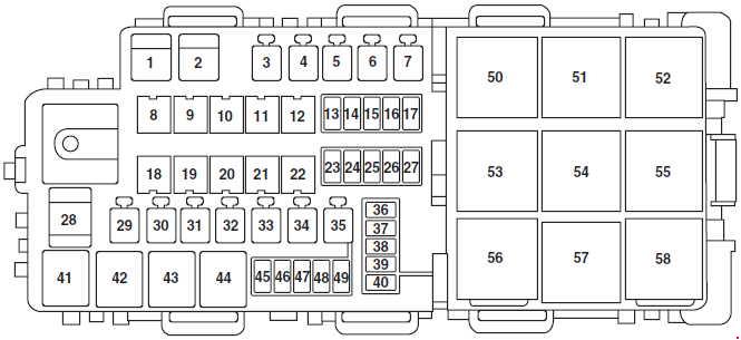
Power distribution box
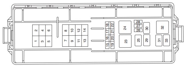
The power distribution box is located in the engine compartment. The power distribution box contains high-current fuses that protect your vehicle’s main electrical systems from overloads.
| Fuse/relay | Ampere rating [A] | Description |
| 1 | 60** | Fuse junction panel |
| 2 | 30** | PCM relay |
| 3 | 60** | Fuse junction panel |
| 4 | — | Not used |
| 5 | — | Not used |
| 6 | — | Not used |
| 7 | 40** | Starter relay, Ignition switch |
| 8 | 20** | Transit relay (export only), Rear foglamps |
| 9 | 40** | Cooling fan relays |
| 10 | — | Not used |
| 11 | — | Not used |
| 12 | — | Not used |
| 13 | 40** | Anti-lock brake module pump feed |
| 14 | — | Not used |
| 15 | 20* | Anti-lock brake module valve solenoid |
| 16 | 20* | Fuel pump relay |
| 17 | 20* | Cell port |
| 18 | 20* | Cigar lighter |
| 19 | 15* | Right headlamp |
| 20 | — | Not used |
| 21 | 15* | Left headlamp |
| 22 | 10* | A/C clutch relay, PCM keep alive power |
| 23 | — | Starter motor relay |
| 24 | — | Fan relay |
| 25 | — | Wiper speed relay |
| 26 | 10* | Alternator |
| 27 | 5* | Rear control unit, Antenna |
| 28 | 15* | HEGO sensor transmission shift solenoid, Canister vent, A/C clutch relay |
| 29 | — | Wiper park relay |
| 30 | — | Fuel pump relay |
| 31 | — | PCM power relay |
| 32 | — | Fan relay |
| 33 | — | A/C clutch relay |
| * Mini Fuses ** Maxi Fuses | ||
WARNING: Terminal and harness assignments for individual connectors will vary depending on vehicle equipment level, model, and market