Buick Park Avenue (2003 – 2005) – fuse box diagram

Buick Park Avenue (2003 – 2005) – fuse box diagram

Year of production: 2003, 2004, 2005

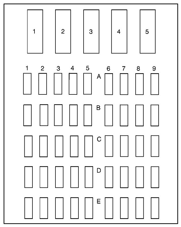
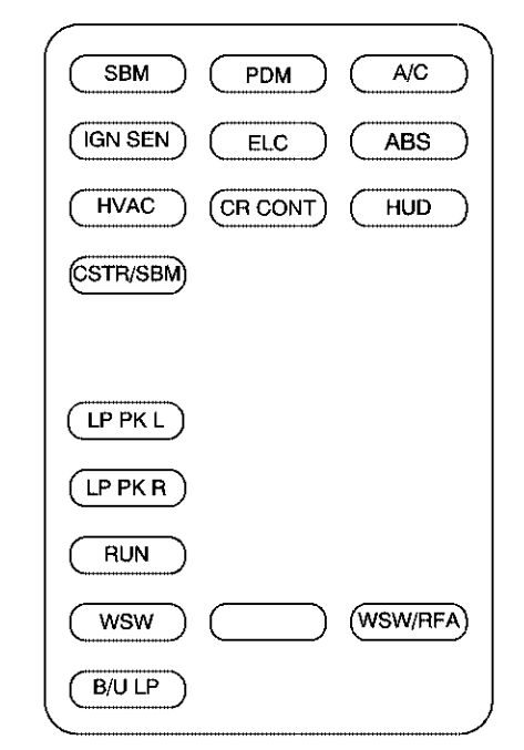
Main Instrument Panel Fuse Block

The main instrument panel fuse block is located under the instrument panel, on the passenger’s side of the vehicle.

Buick Park Avenue - fuse box - main instrument fuse panel
Buick Park Avenue – fuse box – main instrument fuse panel
Fuses Usage
SBM Interior Lamps
PDM PDM Module
A/C HVAC Motor, HVAC Mix Motors
IGN SEN Auto Dimming Mirror, Driver HTS Seat, Rear Defog Relay, MEM Module, Cool LVL Sensor, Passenger Heated Seat
ELC HVAC Flat Pk Mtrs, Electronic Level Control Sensor, Electronic Level Control Sensor (Rear Fuse Block
ABS Anti-Lock Brake System Module
HVAC HVAC Main Con Head, HVAC Programmer, Instrument Panel Cluster
CR CONT Stepper Motor Cruise, Cruise Switch
HUD Head-Up Display Switch, Head-Up Display
CSTR/SBM HVAC Programmer, Instrument Panel Cluster, SBM (275 to LCM) (1135 to BTSI SL)
LP PK L Underhood Lamp, Left Park/Sidemarker, Left Park/Turn Lamp, SBM, Left Tail Signal Lamp, Left Tail/Stoplamp, Left Rear Sidemarker
LP PK R Right Park/Sidemarker Lamp, Right Park/Turn Lamp, Right Tail/Sign Lamp, Right Tail/Stoplamp, Right Rear Sidemarker, Stop/Taillamp, Tail/Signal Lamp, License Lamp, RFA
RUN Run/Accessory
WSW Wiper Motor
Blank Not Used
WSW/RFA Wiper Switch, RFA, Rain Sense
B/U LP Auto Dimming Mirror, Back-Up Lamps

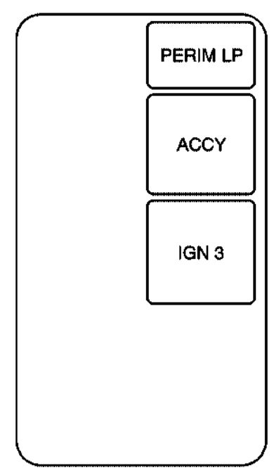
Auxiliary Instrument Panel Fuse Block

The auxiliary instrument panel fuse block is located under the instrument panel, on the passenger’s side of the vehicle.

Buick Park Avenue - fuse box - auxiliary instrument panel
Buick Park Avenue – fuse box – auxiliary instrument panel
Fuses Usage
PERIM LP Perimeter Lamps
ACCY Accessory
IGN 3 Ignition 3

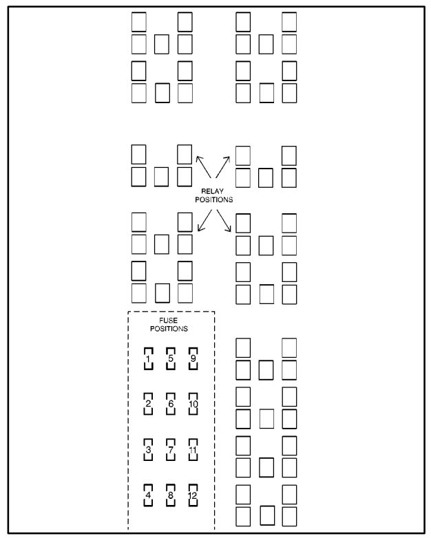
Underhood Fuse Block

There are additional fuses located in the engine compartment on the passenger’s side of the vehicle.
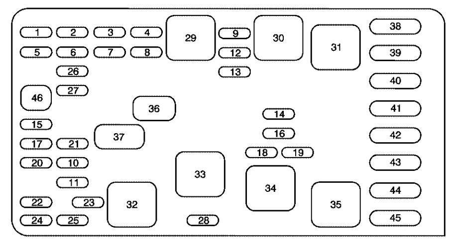
Buick Park Avenue - fuse box - underhood
Buick Park Avenue – fuse box – underhood
Fuses Usage
1 Not Used
2 SBM, LCM
3 Turn Signal
4 Pre-Oxygen Sensor, Post-Oxygen Sensor
5 Air Bag (SIR)
6 Powertrain Control Module
7 Air Conditioning Clutch
8 Ignition Feed
9 Horn Relay
10 Spare
11 Spare
12 Injectors #1-6
13 C-31
14 Right High Beam
15 Spare
16 Left High Beam
17 Spare
18 Right Low Beam
19 Left Low Beam
20 Stop
21 Fuel Pump Relay (Wire in BEC)
22 Run/Crank
23 Powertrain Control Module
24 Parking Lamps
25 Hazard Flashers
26 Spare
27 Spare
28 ABS #2


Relays Usage
29 Ignition
30 Horn
31 Cooling Fan 1
32 Starter
33 Not Used
34 Cooling Fan SP
35 Cooling Fan 2
36 Air Conditioning Clutch
37 Fuel Pump


Fuses Usage
38 Bat #1
39 Blower Motor
40 Cooling Fan 1
41 Headlamp
42 BAT #2
43 Ignition
44 Starter
45 ABS
46 Fuse Puller

Rear Compartment Fuse Block

Additional fuses are located in the fuse center under the rear seat. The rear seat cushion must be removed to access the fuses.
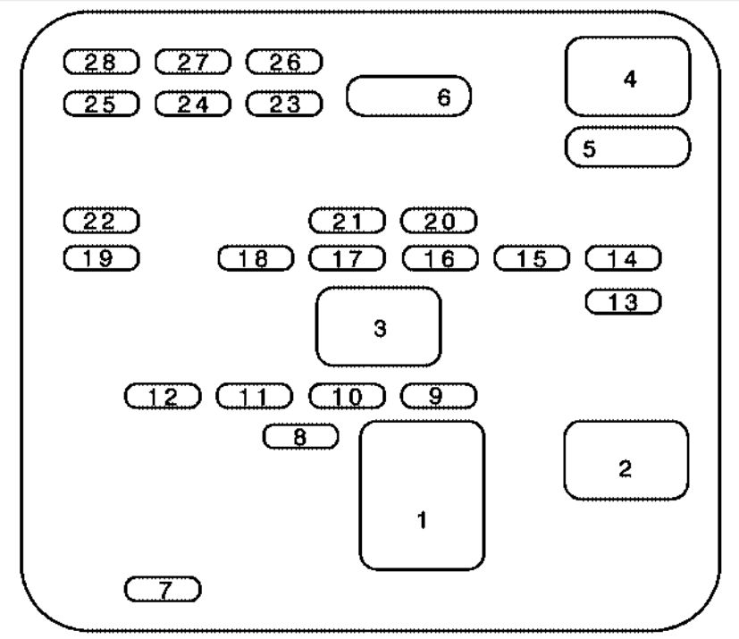
Buick Park Avenue - fuse box - rear compartment
Buick Park Avenue – fuse box – rear compartment
Relays Usage
1 Heated Backlite
2 Retained Accessory Power (RAP)
3 Trunk Release
4 Electronic Level Control
5 Power Seat
6 Electronic Level Control Sensor, Electronic Level Control Compressor Solenoid


Fuses Usage
7 Crank
8 Accessory Outlet
9 Powertrain Control Module for Cruise
10 SBM Module
11 Radio/Phone
12 Sunroof
13 Spare
14 CD Changer, Phone
15 Driver Door Module
16 Spare
17 Radio
18 Driver Heated Seat Module
19 Rear Door Module
20 Trunk Release
21 Spare
22 Instrument Panel Ashtray Cigarette Lighter
23 Spare
24 Spare
25 Passenger Heated Seat Module
26 Right Rear Cig Lighter
27 Left Rear Cig Lighter
28 RFA, Memory Seat Module, Driver Seat Switch

WARNING: Terminal and harness assignments for individual connectors will vary depending on vehicle equipment level, model, and market.

Buick LeSabre (1994) – fuse box diagram

Buick LeSabre (1994) – fuse box diagram

Year of production: 1994

Fuses

The fuse panel is located under the instrument panel, next to the parking brake.

Buick LeSabre - fuse box - under wheel steering
Buick LeSabre – fuse box – under wheel steering
Fuses Ampere rating [A] Usage
1 30 BRKR – Power Window
2 Not Used
3 25 BRKR-Power Seats
4 Not Used
5 Not Used
1A 10 SIR DEMCrank
1B 20 Signal/Cornering/Back-up Lamps
1C 10 SIR
1D 15 Cluster/Telltale/Chime
1E Not Used
2A 10 Spare
2B 15 Spare
2C 20 Spare
2D 25 Spare
2E Not Used
3A Not Used
3B Not Used
3C Not Used
3D Not Used
3E Not Used
4A 10 Interior Illumination
4B Not Used
4C Not Used
4D Not Used
4E Not Used
5A 10 Uplevel HVAC/OiI LeveVLow Coolant
5B 10 ABS
5C 10 Transmission/Cooling Fans
5D 25 Base HVAC
5E Not Used
6A 15 Courtesy LampsPower Mirrors
6B 20 Brake & Hazard Lamps
6C 15 Park Lamps
6D Not Used
6E Not Used
7A Not Used
7B Not Used
7C Not Used
7D Not Used
7E Not Used
8A Not Used
8B Not Used
8C Not Used
8D 10 Radio
8E 25 Wiper/washer
9A 15 Ash Tray/Cigar Lighter
9B 20 Electronic Level Control
9C 10 Radio/Ipnition
9D Not Used
9E 30 Rear Window Defog

WARNING: Terminal and harness assignments for individual connectors will vary depending on vehicle equipment level, model, and market.

Buick LeSabre (1995) – fuse box diagram

Buick LeSabre (1995) – fuse box diagram

Year of production: 1995

Fuses and Circuit Breakers

The fuse panel is located under the instrument panel, next to the parking brake.

Buick LeSabre - fuse box - under wheel steering
Buick LeSabre – fuse box – under wheel steering
Fuses Usage
1 Power Window
2 Not Used
3 BRKR-Power Seats
4 Not Used
5 Not Used
1A SIR DEMCrank
1B Signal/Cornering/Back-up Lamps
1C SIR
1D Cluster/Telltale/Chime
1E Not Used
2A Spare
2B Spare
2C Spare
2D Spare
2E Not Used
3A Not Used
3B Not Used
3C Not Used
3D Not Used
3E Not Used
4A Interior Illumination
4B Not Used
4C Not Used
4D Not Used
4E Not Used
5A Uplevel HVAC/OiI LeveVLow Coolant
5B ABS
5C Transmission/Cooling Fans
5D Base HVAC
5E Not Used
6A Courtesy LampsPower Mirrors
6B Brake & Hazard Lamps
6C Park Lamps
6D Not Used
6E Not Used
7A Not Used
7B Not Used
7C Not Used
7D Not Used
7E Not Used
8A Not Used
8B Not Used
8C Not Used
8D Radio
8E Wiperwasher
9A Ash Tray/Cigar Lighter
9B Electronic Level Control
9C Radio/Ipnition
9D Not Used
9E Rear Window Defog

WARNING: Terminal and harness assignments for individual connectors will vary depending on vehicle equipment level, model, and market.

Buick LeSabre (1996 – 1998) – fuse box diagram

Buick LeSabre (1996 – 1998) – fuse box diagram

Year of production: 1996, 1997, 1998

Driver’s Side Fuse Block

The driver’s side fuse block is to the left of the steering wheel, under the instrument panel.

Buick LeSabre - fuse box - under wheel steering
Buick LeSabre – fuse box – under wheel steering
Fuses Usage
1 Not Used
2 Not Used
3 Power Seats Circuit Breaker
4 Not Used
5 Not Used
1A PASS Key
2A Spare
3A Not Used
4A Not Used
5A Up-Level HVAC, ALM, Cruise Control, Cluster
6A Courtesy Lamps, Power Mirrors
7A Not Used
8A Perimeter Lighting
9A Not Used
1B Turn Signal, Back-Up Lamps, BTSI
2B Spare
3B Not Used
4B Not Used
5B Anti-Lock Brake System, Computer Command Control
6B Brake and Hazard Lamps
7B Not Used
8B Interior Lighting
9B Cigarette Lighter
1C Air Bag System
2C Spare
3C Not Used
4C Not Used
5C Cooling Fans, Transaxle
6C Parking Lamps, Interior Lamps
7C Not Used
8C Parking Lamps
9C Radio, Cluster
1D Telltale, Chime, Cluster, RAC, LCM
2D Spare
3D Heated Mirrors
4D Not Used
5D Base NC
6D Not Used
7D TCC
8D Radio
9D Not Used
1E Not Used
2E Air Bag System, PASS-Key
3E Not Used
4E Not Used
5E Rear Defog
6E Not Used
7E Miscellaneous Engine-Non OBD II
8E Wipers, Washer
9E Not Used

Passenger’s Side Fuse Block

Additional fuses are located in the relay center, on the passenger’s side, below the instrument panel.

Buick LeSabre - fuse box - instrument pane (passengers side)
Buick LeSabre – fuse box – instrument pane (passengers side)
Fuses Usage
1 Door Locks
2 Trunk Release, RAC
3 Horns
4 Not Used
5 Miscellaneous Engine Controls
6 Fuel Pump
7 Injectors
8 Powertrain Control Module
9 Not Used
10 Not Used
11 A/C Programmer
12 Not Used

WARNING: Terminal and harness assignments for individual connectors will vary depending on vehicle equipment level, model, and market.

Buick LeSabre (1999) – fuse box diagram

Buick LeSabre (1999) – fuse box diagram

Year of production: 1999

Driver’s Side Fuse Block

The driver’s side fuse block is to the left of the steering wheel, under the instrument panel.

Buick LeSabre - fuse box - under wheel steering
Buick LeSabre – fuse box – under wheel steering
Fuses Usage
1 Not Used
2 Not Used
3 Power Seats Circuit Breaker
4 Not Used
5 Not Used
1A PASS Key
2A Spare
3A Not Used
4A Not Used
5A Auto HVAC, ALM, Cruise Control, Cluster
6A Courtesy Lamps, Power Mirrors
7A Not Used
8A Perimeter Lighting
9A Not Used
1B Turn Signal, Back-Up Lamps, BTSI
2B Spare
3B Not Used
4B Not Used
5B Anti-Lock Brake System, Computer Command Control
6B Brake and Hazard Lamps
7B Not Used
8B Interior Lighting
9B Cigarette Lighter
1C Air Bag System
2C Spare
3C Not Used
4C Not Used
5C Cooling Fans, Transaxle
6C Parking Lamps, Interior Lamps
7C Not Used
8C Parking Lamps
9C Radio, Cluster
1D Telltale, Chime, Cluster, RAC, LCM
2D Spare
3D Heated Mirrors
4D Not Used
5D Manual A/C
6D Not Used
7D TCC
8D Radio
9D Not Used
1E Not Used
2E Air Bag System, PASS-Key
3E Not Used
4E Not Used
5E Rear Defog
6E Not Used
7E Miscellaneous Engine-Non OBD II
8E Wipers, Washer
9E Not Used


Passenger’s Side Fuse Block

Additional fuses are located in the relay center, on the passenger’s side, below the instrument panel.

Buick LeSabre - fuse box - instrument pane (passengers side)
Buick LeSabre – fuse box – instrument pane (passengers side)


Fuses Usage
1 Door Locks
2 Trunk Release, RAC
3 Horns
4 Not Used
5 Miscellaneous Engine Controls (OBD II)
6 Fuel Pump
7 Injectors
8 Powertrain Control Module
9 Not Used
10 Not Used
11 A/C Programmer
12 Not Used

WARNING: Terminal and harness assignments for individual connectors will vary depending on vehicle equipment level, model, and market.

RAM 4500 (from 2016) – fuse box diagram

RAM 4500 (from 2016) – fuse box diagram

Year of production: 2016, 2017

Power Distribution Center

The Power Distribution Center is located in the engine compartment near the battery.

Cavity Cartridge fuse Micro Fuse Description
F01 80 Rad Fan Control Module – If equipped
F03 60 Rad Fan – If Equipped
F05 40 Compressor for Air Suspension – If Equipped
F06 40 Antilock Brakes/Electronic Stability Control Pump
F07 40 Starter Solenoid
F08 20 (1500 LD/Cummins Diesel Emissions Diesel – If Equipped
F09 40 (Special Services
Vehicle & Cummins
Diesel)
Diesel Fuel Heater – If Equipped
30 (1500 LD Diesel)
F10 40 Body Controller / Exterior Lighting #2
50 Body Controller / Exterior Lighting #2 – If Equipped with Stop/Start
F11 30 Integrated Trailer Brake Module – If Equipped
F12 40 Body Controller #3 / Interior Lights
F13 40 Blower Motor
F14 40 Body Controller #4 / Power Locks
F16 30 Smart Bar – If Equipped
F19 20 (1500 LD Diesel) SCR – If Equipped
30 (Cummins Diesel)
F20 30 Passenger Door Module
F21 30 Drive Train Control Module
F22 20 Engine Control Module
30 (Cummins Diesel)
F23 30 Body Controller #1
F24 30 Driver Door Module
F25 30 Front Wiper
F26 30 Antilock Brakes/Stability Control Module/Valves
F28 20 Trailer Tow Backup Lights – If Equipped
F29 20 Trailer Tow Parking Lights – If Equipped
F30 30 Trailer Tow Receptacle
F31 30 (1500 LD Diesel) Urea Heater Control – If Equipped
F32 Spare fuse
F33 20 Special Services Vehicle Only
F34 30 Vehicle System Interface Module #2 – If Equipped
F35 30 Sunroof – If Equipped
F36 30 Rear Defroster– If Equipped
F37 30 Cummins Diesel Fuel Heater #2 – If Equipped
F38 30 Power Inverter 115V AC– If Equipped
F39 30 Power Outlet – Special Services Only
F41 10 Active Grill Shutter – If Equipped
F42 20 Horn
F44 10 Diagnostic Port
F46 10 Upfitter – If Equipped
F49 10 Instrument Panel Cluster
F50 20 Air Suspension Control Module – If Equipped
F51 10 Ignition Node Module / Keyless Ignition
F52 5 Battery Sensor
F53 20 Trailer Tow – Left Turn/Stop Lights
F54 20 Adjustable Pedals
F56 15 Additional Diesel Content – If Equipped
F57 20 Transmission
F58 20 Spare Fuse
F59 10 SCR Relay – If Equipped
F60 15 Underhood Lamp
F61 10 (1500 LD Diesel & Cummins
Diesel)
PM Sensor – If Equipped
F62 10 Air Conditioning Clutch
F63 20 IgnitionCoils (Gas), Urea Heater (Diesel)
F64 25 Fuel Injectors / Powertrain
F65 10 USB interface
F66 10 Sunroof / Passenger Window Switches /Rain Sensor
F67 10 CD / DVD / Bluetooth Hands-free Module – If Equipped
F69 15 Mod SCR 12V – If Equipped
F70 30 Fuel Pump Motor
F71 25 Amplifier
F72 10 PM Sensor – If Equipped
F73 20 Fuel Transfer Pump (HD Only) – If Equipped
F74 20 (Gas engine & 1500 LD Diesel) Brake Vacuum Pump Gas/Diesel – If Equipped
F75 10 Coolant Temperature Valve Actuator
F76 10 Antilock Brakes/Electronic Stability Control
F77 10 Drivetrain Control Module/Front Axle Disconnect Module
F78 10 Engine Control Module / Electric Power Steering
F79 15 Clearance Lights
F80 10 Universal Garage Door Opener / Compass
F81 20 Trailer Tow Right Turn/Stop Lights
F82 10 Steering Column Control Module/ Cruise Control
F84 15 Switch Bank/Instrument Cluster
F85 10 Airbag Module
F86 10 Airbag Module
F87 10 Air Suspension-If Equipped / Trailer Tow / Steering Column Control Module
F88 15 Instrument Panel Cluster
F90 20 Power Outlet (Rear seats) Customer Selectable
F91
F93 20 Cigar Lighter
F94 10 Shifter / Transfer Case Module
F95 10 Rear Camera / Park Assist
F96 10 Rear Seat Heater Switch
F97 25 Rear Heated Seats & Heated Steering Wheel – If Equipped
F98 25 Front Heated Seats – If Equipped
F99 10 Climate Control
F100 10 Upfitters – If Equipped
F101 15 Electrochromatic Mirror / Smart High Beams – If Equipped
F104 20 Power Outlets (Instrument Panel/Center Console)

WARNING: Terminal and harness assignments for individual connectors will vary depending on vehicle equipment level, model, and market.

RAM 4500 (2013 – 2015) – fuse box diagram

RAM 4500 (2013 – 2015) – fuse box diagram

Year of production: 2013, 2014, 2015

Power Distribution Center

The Power Distribution Center is located in the engine compartment near the battery.

Cavity Cartridge fuse Micro Fuse Description
F01 80 Rad Fan Control Module – If equipped
F03 60 Rad Fan – If Equipped
F05 40 Compressor for Air Suspension – If Equipped
F06 40 Antilock Brakes/Electronic Stability Control Pump
F07 40 Starter Solenoid
F08 30 Emissions Diesel – If Equipped
F09 40 Diesel Fuel Heater – If Equipped
F10 40 Body Controller / Exterior Lighting #2
50 Body Controller / Exterior Lighting #2 – If Equipped with Stop/Start
F11 30 Integrated Trailer Brake Module – If Equipped
F12 40 Body Controller #3 / Interior Lights
F13 40 Blower Motor
F14 40 Body Controller #4 / Power Locks
F15 30 Electric Park Brake Right Side – If Equipped
F19 30 SCR – If Equipped
F20 30 Passenger Door Module
F21 30 Drive Train Control Module
F22 20 Engine Control Module
F23 30 Body Controller #1
F24 30 Driver Door Module
F25 30 Front Wiper Low Speed
30 Front Wiper High Speed
F26 30 Antilock Brakes/Stability Control Module/Valves
F28 20 Trailer Tow Backup Lights – If Equipped
F29 20 Trailer Tow Parking Lights – If Equipped
F30 30 Trailer Tow Receptacle
F32 30 Drive Train Control Module – If Equipped
F33 20 Diesel Fuel Heater #1 – If Equipped /Rear Blower – If Equipped
F34 30 Vehicle System Interface Module #2 – If Equipped
F35 30 Sunroof – If Equipped
F36 30 Rear Defroster– If Equipped
F37 30 Diesel Fuel Heater #2 if equipped
F38 30 Power Inverter 115V AC– If Equipped
F39 30 Vehicle System Interface Module #1– If Equipped
F41 10 Active Grill Shutter
F42 20 Horn
F43 10 Snow Plow (Left) – If Equipped
F44 10 Diagnostic Port
F46 10 Tire Pressure Monitor
F47 10 Snow Plow (Right) – If Equipped
F49 10 Instrument Panel Cluster
F50 20 Air Suspension Control Module – If Equipped
F51 10 Ignition Node Module / Keyless Ignition
F52 5 Battery Sensor
F53 20 Trailer Tow – Left Turn/Stop Lights
F54 20 Adjustable Pedals
F55 20 E38 Radio – If Equipped
F56 15 Additional Diesel Content – If Equipped
F57 20 Transmission
F58 20 (Gas engine) Engine Cooling Pump
25 (Diesel engine)
F60 15 Underhood Lamp
F61 20 Power Take-off Unit – If Equipped
F62 10 Air Conditioning Clutch
F63 20 IgnitionCoils (Gas), Urea Heater (Diesel)
F64 25 Fuel Injectors / Powertrain
F65 10 USB interface
F66 10 Sunroof / Passenger Window Switches /Rain Sensor
F67 10 CD / DVD / Bluetooth Hands-free Module – If Equipped
F69 15 Mod SCR 12V – If Equipped
F70 30 Fuel Pump Motor
F71 25 Amplifier
F72 10 Voltage Stabilizer Modules – If Equipped
F74 20 (Gas engine) Brake Vacuum Pump Gas/Diesel – If Equipped
10 (Diesel engine)
F75 10 Coolant Temperature Valve Actuator
F76 10 Antilock Brakes/Electronic Stability Control
F77 10 Drivetrain Control Module/Front Axle Disconnect Module
F78 10 Engine Control Module / Electric Power Steering
F79 15 Clearance Lights
F80 10 Universal Garage Door Opener / Compass
F81 20 Trailer Tow Right Turn/Stop Lights
F82 10 Steering Column Control Module/ Cruise Control
F84 15 Switch Bank/Instrument Cluster
F85 10 Airbag Module
F86 10 Airbag Module
F87 10 Air Suspension-If Equipped / Trailer Tow / Steering Column Control Module
F88 15 Instrument Panel Cluster
F90 20 Power Outlet (Rear seats) Customer Selectable
F91
F93 20 Cigar Lighter
F94 10 Shifter / Transfer Case Module
F95 10 Rear Camera / Park Assist
F96 10 Rear Seat Heater Switch
F97 25 Rear Heated Seats & Heated Steering Wheel – If Equipped
F98 25 Front Heated Seats – If Equipped
F99 10 Climate Control
F101 15 Electrochromatic Mirror / Smart High Beams – If Equipped
F104 20 Power Outlets (Instrument Panel/Center Console)

WARNING: Terminal and harness assignments for individual connectors will vary depending on vehicle equipment level, model, and market.

RAM 4500 (2012) – fuse box diagram

RAM 4500 (2012) – fuse box diagram

Year of production: 2012

Totally Integrated Power Module

The totally integrated power module (TIPM) is located in the engine compartment near the battery.

Cavity Cartridge fuse Mini Fuse Description
J01 40 Trailer Tow
J02 30 Electric Brake
J03 30 Diesel Powertrain Control Module – If Equipped
J04 25 Driver Door Node
J05 25 Passenger Door Node
J06 40 Antilock Brakes Pump/Stability Control System
J07 30 Antilock Brakes Valve/Stability Control System
J08 40 Power Seat
J10 30 Sway Bar Module – If Equipped
J11 30 Transfer Case Module
J12 30 Rear Defroster
J13 60 Main Ignition Off Draw (IOD) Fuse
J14 20 Trailer Tow Lamps/Park Lamps
J15 40 Front Blower
J17 40 Starter Motor Solenoid
J18 20 Powertrain Control Module Transmission Range
J19 60 Rad Fan Motor HI/Rad Fan Motor Low
J20 30 Front Wiper Ground/Low/High
J21 20 Washer Control
J22 25 Sunroof Module
M1 15 Stop Switch Lamp
M5 25 115V AC Inverter
M6 20 Power Outlet (Instrument Panel or Front Console)/Rain Snsr
M7 20 Power Outlet (Rear Console or Center Seat)
M8 20 Front Heated Seat & Steering Wheel
M9 20 Rear Heated Seats
M10 15 Hands Free Module/Vanity Lamp/Universal GarageDoor Opener Module
M11 10 Climate Control System
M12 30 Radio/Amplifier
M13 20 Main #2 Instrument Cluster/Wireless Control Module/ITM/
Siren/Multifunction Switch (Steering Column Module)
M14 20 Back Up Camera (Domestic Only)
M15 20 Power Seat Module(s)/Audio Telematics/Daytime Running Lights Relay/Instrument Cluster/Transfer Case Module
M16 10 Airbag Module
M18 15 Center Stop Lamp
M19 25 Automatic Shutdown 1 and 2
M20 15 Instrument Cluster Interior Lighting /Sw Steering Wheel/Sw Bank
M21 20 Automatic Shutdown 3
M22 10 Horns (Low/High) – Right
M23 10 Horns (Low/High) – Left
M25 20 Fuel Pump Motor/Diesel Lift Pump – If Equipped
M26 10 Driver’s Door Switch
M27 10 Ignition Switch
M28 15 Powertrain Control Module
M29 10 Tire Pressure Monitor
M30 15 J1962 Diag Connector
M31 20 Back-Up Lamps
M32 10 Airbag Module
M33 10 Powertrain Control Module
M34 10 Park Assist Module/Climate Control System Module/IR Sensor/Compass Module
M35 15 Left Front & Rear Parklamps
M36 20 Power Outlet (Instrument Panel or Center Console)
M37 10 Antilock Brakes/Stability Control System Module/Stoplamp Switch
M38 25 All Door Lock &Unlock

WARNING: Terminal and harness assignments for individual connectors will vary depending on vehicle equipment level, model, and market.

RAM 4500 (2011) – fuse box diagram

RAM 4500 (2011) – fuse box diagram

Year of production: 2011

Totally Integrated Power Module

The totally integrated power module (TIPM) is located in the engine compartment near the battery.

Cavity Cartridge fuse Mini Fuse Description
J01 30 Bat – Presafe #1/CM2200
J02 30 Bat – Trailer Tow Main
J03 25 Bat – Passenger Door Node
J04 40 Bat – ABS Pump
J05 30 Bat – ABS Valve
J06 30 Bat – H/Lamp Wash/MTV/CM2200/Elec Vac Pump
J07 25 Bat – Driver Door Node
J08 30 Bat – DTCM/Axle Locks
J09 30 Bat – Plg/Electric Brake
J10 40 Bat – L/Bar/Off-Road
J11 30 Bat – Sway/Thatchum/Rear Doors
J12 40 Starter Solenoid
J13  60 Bat – Rad Fan #1/#2/SSR
J14 40 Bat – Folding Seat/PZEV
J15 60 Bat – IOD Main
J16 40 Frt HVAC Motor
M17 25 Bat – Sunroof/Skylight
M18 25 TCM/Trans Range
M19 5 Ign R/ACC – Sunroof/Window Sw Illum
M20 25 Frt Wiper
M21 25 Door Locks
M22 20 Fuel Pump
M23 20 Bat – Trlr Light/Pre-Safe #2
M24 20 Bat – Trlr Tow BUX/HGM
M25 10 Bat – J1962 Diag/Mirrors
M26 10 Bat – Ign Sw, WIN, PASS
M27 15 Bat – CHMSL/Brake Sw
M28 10 Bat – Corax TPM/PEM/HVAC Htr Pump
M29 15 Bat – Folding Mirror
M30 25 Bat – Inverter
M31 20 Bat – Pwr Out #1
M32 20 Fr/Rr Washer
M33 15 Bat – NGC/EATX/PCM
M34 15 Bat – CCN/Interior Light/SCM/Sw Bank
M35 20 Htd Seat/Htd Str Wheel/Rear Htd Seat
M36 20 Ign R-Rear Seat/Steer Wheel
M37 10 Horn #1
M38 30 IOD-CCN/Interior Mods
M39 30 IOD-Amp/Radio
M40 25 Rear Wiper
M41 15 IOD-SDARS/VES 2–3/DVD/HFM/UGDO/Vanity Lamp
M42 10 IOD-HVAC, U/Hood Lamp
M43 10 Horn #2
M44 10 IGN R/S-ORC/OCM
M45 10 IGN R-ORC/Trail Tow (BUX) Sense
M46 20 IGN R-Trail Tow (BUX)
M47 10 IGN R-H/Lamp Wash/HVAC/Park Assist/Ir Sns
M48 20 IGN R/ACC-Pwr Outlet #2
M49 20 IGN R/ACC/Bat-Pwr Outlet #3
M50 25 ASD #1, #2
M51 20 ASD #3
M52 10 IGN R/S-SWAY/TCASE/DTCM/FAD/TRLR BRAKE MOD
M53 15 IGN R/S-MFSW/CNN/SCM/TPM/RR View
M54 20 IOD – Spare

WARNING: Terminal and harness assignments for individual connectors will vary depending on vehicle equipment level, model, and market.

RAM 4500 (2010) – fuse box diagram

RAM 4500 (2010) – fuse box diagram

Year of production: 2010

Totally Integrated Power Module

The totally integrated power module (TIPM) is located in the engine compartment near the battery.

Cavity Cartridge fuse Mini Fuse Description
J01 30 Bat – Presafe #1
J02 30 Bat – Trailer Tow Main
J03 25 Bat – Passenger Door Node
J04 40 Bat – ABS Pump
J05 30 Bat – ABS Valve
J06 30 Bat – H/Lamp Wash/MTV/CM2200/Elec Vac Pump
J07 25 Bat – Driver Door Node
J08 30 Bat – DTCM/Axle Locks
J09 30 Bat – Plg/Electric Brake
J10 40 Bat – L/Bar/Off-Road
J11 30 Bat – Sway/Thatchum/Rear Doors
J12 40 Starter Solenoid
J13  60 Bat – Rad Fan #1/#2/SSR
J14 40 Bat – Folding Seat/PZEV
J15 60 Bat – IOD Main
J16 40 Frt HVAC Motor
M17 25 Bat – Sunroof/Skylight
M18 25 TCM/Trans Range
M19 5 Ign R/ACC – Sunroof/Window Sw Illum
M20 25 Frt Wiper
M21 25 Door Locks
M22 20 Fuel Pump
M23 20 Bat – Trlr Light/Pre-Safe #2
M24 20 Bat – Trlr Tow BUX/
HGM
M25 10 Bat – J1962 Diag/Mirrors
M26 10 Bat – Ign Sw, WIN, PASS
M27 15 Bat – CHMSL/Brake Sw
M28 10 Bat – Corax TPM/PEM/HVAC Htr Pump
M29 15 Bat – Folding Mirror
M30 25 Bat – Inverter
M31 20 Bat – Pwr Out #1
M32 20 Fr/Rr Washer
M33 15 Bat – NGC/EATX/PCM
M34 15 Bat – CCN/Interior Light/SCM/Sw Bank
M35 20 Ign R-Frt Seat/Vent
M36 20 Ign R-Rear Seat/Steer Wheel
M37 10 Horn #1
M38 30 IOD-CCN/Interior Mods
M39 30 IOD-Amp/Radio
M40 25 Rear Wiper
M41 15 IOD-SDARS/VES 2–3/DVD/HFM/UGDO/Vanity Lamp
M42 10 IOD-HVAC, U/Hood Lamp
M43 10 Horn #2
M44 10 IGN R/S-ORC/OCM
M45 10 IGN R-ORC/Trail Tow (BUX) Sense
M46 20 IGN R-Trail Tow (BUX)
M47 10 IGN R-H/Lamp Wash/HVAC/Park Assist/Ir Sns
M48 20 IGN R/ACC-Pwr Outlet #2
M49 20 IGN R/ACC/Bat-Pwr Outlet #3
M50 25 ASD #1, #2
M51 20 ASD #3
M52 10 IGN R/S-SWAY/TCASE/DTCM/FAD
M53 15 IGN R/S-MFSW/CNN/SCM/TPM/RRView
M54 20 IOD – Spare

WARNING: Terminal and harness assignments for individual connectors will vary depending on vehicle equipment level, model, and market.