Seat Cordoba (2005) – fuse box diagram
Year of production: 2005
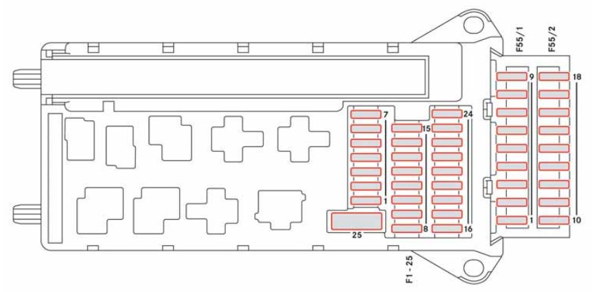
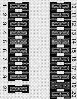
Fuse box
The fuses are located on the left hand side of the dash panel behind a cover.
| Number | Component | Ampers |
| 1 | — | — |
| 2 | ABS/ESP | 10 |
| 3 | — | — |
| 4 | Brake light, clutch | 5 |
| 5 | Engine control unit (petrol) | 5 |
| 6 | Dipped beam, right | 5 |
| 7 | Dipped beam, left | 5 |
| 8 | Mirror heating control | 5 |
| 9 | Lambda probe | 10 |
| 10 | “S” signal1). Radio control | 5 |
| 11 | — | — |
| 12 | Height adjustment headlights | 5 |
| 13 | Level sensor/oil pressure | 5 |
| 14 | Additional engine heating/Oil pump | 10 |
| 15 | Automatic gearbox control | 10 |
| 16 | Heated seats | 15 |
| 17 | Engine control unit | 5 |
| 18 | Instrument panel/Heating and ventilation, Navigation, Height adjustment headlights, Electric mirror | 10 |
| 19 | Reverse light | 15 |
| 20 | Windshield washer pump | 10 |
| 21 | Main beam, right | 10 |
| 22 | Main beam, left | 10 |
| 23 | License plate light/pilot light for side light | 5 |
| 24 | Windshield wiper | 10 |
| 25 | Sprayers (petrol) | 10 |
| 26 | Brake light switch/ESP | 10 |
| 27 | Instrument panel/Diagnosis | 5 |
| 28 | Control: glove compartment light, boot light, interior light sun roof | 10 |
| 29 | Climatronic | 5 |
| 30 | — | — |
| 31 | Electronic window, left | 25 |
| 32 | Control central locking | 15 |
| 33 | Self-fed alarm horn | 15 |
| 34 | Current supply | 15 |
| 35 | Open roof | 20 |
| 36 | Engine electro-fan heating/Ventilation | 25 |
| 37 | Pump/headlight washers | 20 |
| 38 | Fog lights, rear fog lights | 15 |
| 39 | Control petrol engine unit | 15 |
| 40 | Control diesel engine unit | 20 |
| 41 | Fuel level indicator | 15 |
| 42 | Transformer ignition | 15 |
| 43 | Dipped beam, right | 15 |
| 44 | Electric window, rear left | 25 |
| 45 | Electric window, front right | 25 |
| 46 | Control windshield wipers | 20 |
| 47 | Control heated rear windshield | 20 |
| 48 | Control turn signals | 15 |
| 49 | Lighter | 15 |
| 50 | Current rain sensor/central locking | 20 |
| 51 | Radio/CD/GPS | 20 |
| 52 | Horn | 20 |
| 53 | Dipped beam, left | 15 |
| 54 | Electric window, rear right | 25 |
| 1) The “S” signal is a system which incorporates steering wheel lock and ignition. Once the ignition is switched off and without removing the key from the ignition this function allows you to switch on some of the electrical equipment such as the car radio, the courtesy light, etc. This function is deactivated once the key is removed from the ignition. | ||
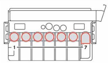
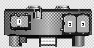
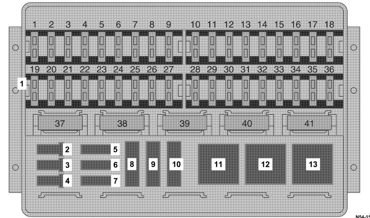
Fuse box in the engine compartment on the battery
Metal fuses
| Number | Component | Ampers |
| 1 | Alternator/Ignition | 175 |
| 2 | Distribution input potential passenger cabin | 110 |
| 3 | Pump power steering | 50 |
| 4 | SLP (petrol)/Preheating spark plugs (diesel) | 50 |
| 5 | Electro-fan heater/climate fan | 40 |
| 6 | ABS control | 40 |
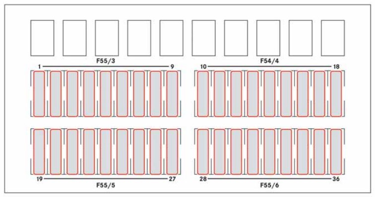
Non-metallic fuses
| Number | Component | Ampers |
| 7 | ABS control | 25 |
| 8 | Electro fan heater/climate fan | 30 |
| 9 | — | — |
| 10 | Wiring control | 5 |
| 11 | Climate fan | 5 |
| 12 | — | — |
| 13 | Control Jatco automatic gearbox | 5 |
| 14 | — | — |
| 15 | — | — |
| 16 | — | — |
WARNING: Terminal and harness assignments for individual connectors will vary depending on vehicle equipment level, model, and market.