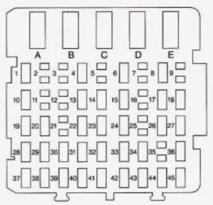
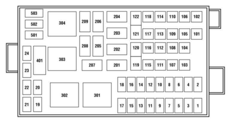
| Fuse/relay location |
Ampere rating [A] |
Usage |
| 1 |
15* |
Park lamps, Roof lamps |
| 2 |
25* |
Cummins Powertrain Control module (PCM) |
| 15* |
Foglamps (SuperCrewzer only) |
| 3 |
10* |
Generator |
| 4 |
15* |
Water pump |
| 5 |
15* |
CAT air intake heater relay, Cummins PCM |
| 6 |
20* |
CAT PCM, Cummins PCM |
| 7 |
15* |
Stop lamps |
| 8 |
25* |
CAT fuel heater |
| 9 |
30* |
Trailer hook-up lamps (SuperCrewzer only) |
| 10 |
15* |
Shift modulator (Allison AT transmission only) (expect for F-650 SuperCrewzer and Catepillar/Cummins) |
| 11 |
20* |
Allision MD transmission, Allision 2000/2400 transmission |
| 12 |
10* |
Keyless entry module (SuperCrewzer only) |
| 13 |
10* |
Park brake adjustment module (SuperCrewzer only) |
| 14 |
— |
— |
| 15 |
7,5* |
Body builder perp (hydraulic brake vehicle only) |
| 16 |
10* |
Allision 2000/2400 transmission (expect F650 SuperCrewzer) |
| 17 |
5* |
Radio (SuperCrewzer only) |
| 18 |
— |
— |
| 19 |
— |
— |
| 20 |
— |
— |
| 21 |
10* |
GEM (hydraulic brake vehicle only) |
| 22 |
— |
— |
| 23 |
— |
— |
| 24 |
— |
— |
| 101 |
40** |
Anit-lock Brake System (ABS) (air brake vehicle only) |
| 102 |
20** |
Body builder prep run fed |
| 103 |
50** |
Ignition switch (Junction box fuses 8, 9, 11, 19, 20, 22, 23, 24, 25, 29, 30, 31) |
| 104 |
20** |
Power point |
| 105 |
20** |
Power door loscks |
| 106 |
30** |
Headlamps |
| 107 |
50** |
Junction box battery feed (fuses 1, 2, 3, 4, 12, 13, 14, 15) |
| 108 |
40** |
Cummins fuel heater |
| 109 |
40** |
Power windows |
| 110 |
30** |
Power seats (SuperCrewzer only) |
| 111 |
30** |
Body builder prep |
| 112 |
40* |
Blower motor |
| 113 |
30** |
Heated seats (SuperCrewzer only) |
| 114 |
30** |
E-brake (SuperCrewzer only) |
| 115 |
40** |
Ignition switch (Junction box fuses 5, 8, 9, 11, 21) |
| 116 |
30** |
Body builder prep |
| 117 |
20** |
7.3L Power Stroke PCM |
| 118 |
30** |
IDM (7.3L Power Stroke only) |
| 119 |
60** |
Hydraulic ABS, Air brake trailer tow fuse block |
| 120 |
| 121 |
60** |
Hydromax motor, Air brake trailer tow fuse block |
| 122 |
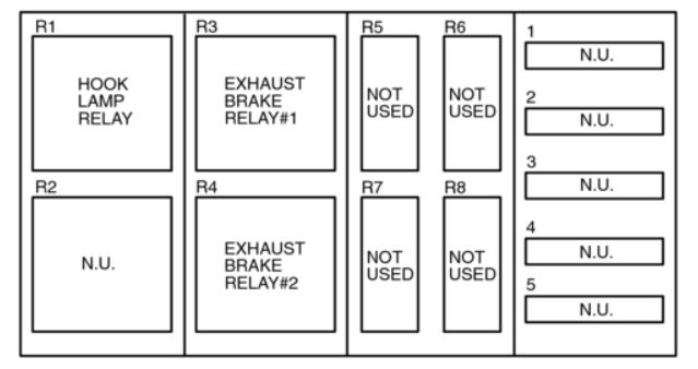
| 201 |
— |
Washer pump relay |
| 202 |
— |
Wiper speed relay |
| 203 |
— |
Wiper run/park relay |
| 204 |
— |
7.3L Power Stroke neutral start relay, Stoplamp relay (CATR and Cummins only) |
| 205 |
— |
Right-hand stop/turn relay |
| 206 |
— |
Left-hand stop/turn relay |
| 207 |
— |
Shift modulator relayu (CAT and Power Stroke only), Cummins VP-44 Relay, A/C high-pressure relay (SuperCrewzer only) |
| 208 |
— |
Back-up lamps relay |
| 209 |
— |
Stop lamps relay, Foglamps relay (SuperCrewzer only) |
| 301 |
— |
Fuel heater relay (CAT and Cummins only)/7.3L Power Stroke PCM relay) |
| 302 |
— |
Parki lamps relay |
| 303 |
— |
Blower motor relay |
| 304 |
— |
Air ABS relay |
| 401 |
— |
— |
| 501 |
— |
— |
| 502 |
— |
— |
| 503 |
Diode |
7.3L Power Stroke PCM diode |
| * Mini Fuses
** Maxi Fuses |