GMC Acadia (2007 – 2008) – fuse box diagram
Year of production: 2007, 2008
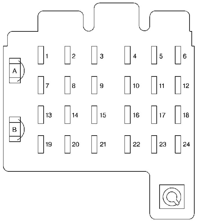
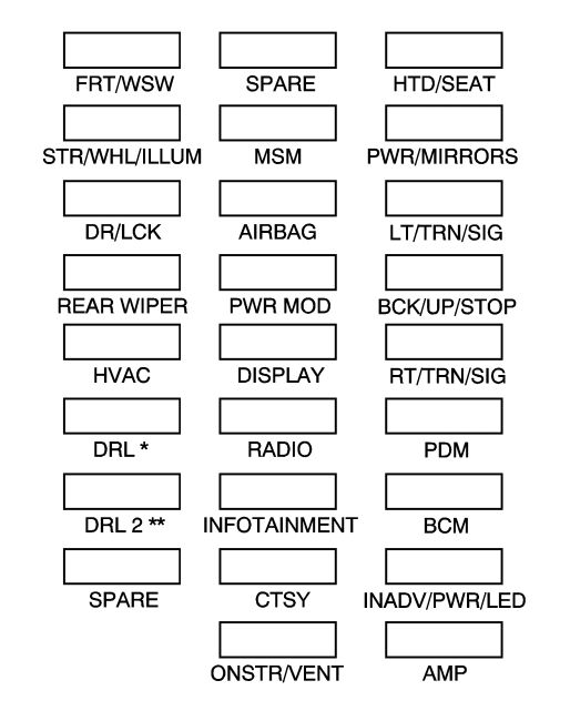
Instrument Panel Fuse Block
The instrument panel fuse block is located under the instrument panel on the passenger side of the vehicle.
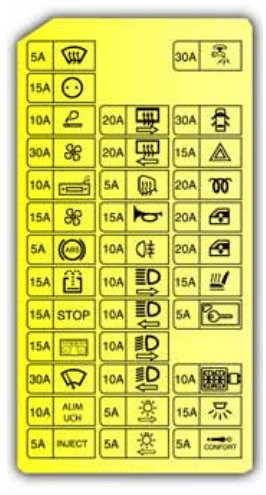
Fuse side
| Fuses | Usage |
| FRT/WSW | Front Windshield Wipe |
| SPARE | Spare |
| HTD/SEAT | Front Heated Seats |
| STR/WHL/ILLUM | Steering Wheel Illumination |
| MSM | Memory Seat Module |
| PWR/MIRRORS | Power Mirrors |
| DR/LCK | Door Locks |
| AIRBAG | Airbag System |
| LT/TRN/SIG | Driver’s Side Turn Signal |
| REAR WIPER | Rear Window Wiper |
| PWR MOD | PassKey Module, Body Control Module |
| BCK/UP/STOP | Back-up Lamps, Stoplamps |
| HVAC | Climate Control System |
| DISPLAY | Display |
| RT/TRN/SIG | Passenger’s Side Turn Signal |
| DRL* | Daytime Running Lamps |
| RADIO | Radio |
| PDM | Power Mirrors, Liftgate Release |
| DRL 2** | Infotainment System |
| INFOTAINMENT | Infotainment System |
| BCM | Body Control Module |
| SPARE | Spare |
| CTSY | Dome Lamps |
| INADV/PWR/LED | Interior Lamps |
| ONSTR/VENT | Emissions |
| AMP | Audio Amplifier |
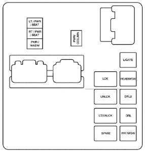
Relay side
| Relays | Usage |
| LT/PWR/SEAT | Driver’s Side Power Seat Relay |
| RT/PWR/SEAT | Passenger’s Side Power Seat Relay |
| PWR/WNDW | Power Windows Relay |
| PWR/COLUMN | Power Steering Column Relay |
| L/GATE | Liftgate Relay |
| LCK | Power Lock Relay |
| REAR/WSW | Rear Window Washer Relay |
| UNLCK | Power Unlock Relay |
| DRL2 | Daytime Running Lamps 2 Relay |
| LT/UNLCK | Driver’s Side Unlock Relay |
| DRL | Daytime Running Lamps Relay |
| SPARE | Spare |
| FRT/WSW | Front Windshield Washer Relay |
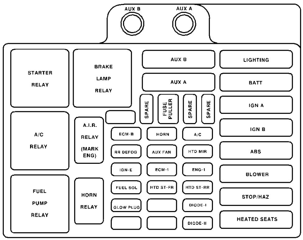
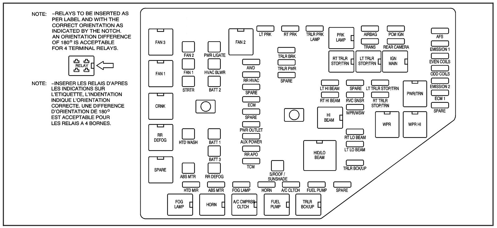
Underhood Fuse Block
The underhood fuse block is located in the engine compartment, on the passenger’s side of the vehicle.
| Fuses | Usage |
| LT PRK | Left Parking Lamp |
| RT PRK | Right Parking Lamp |
| TRLR PRK LAMP | Trailer Parking Lamps |
| AIRBAG | Airbag System |
| PCM IGN | Powertrain Control Module Ignition |
| AFS | Adaptive Forward Lighting System |
| TRANS | Transmission |
| REAR CAMERA | Rear Camera |
| EMISSION 1 | Antilock Brakes System 2 |
| TRLR BRK | Trailer Brake |
| AWD | All-Wheel-Drive System |
| TRLR PWR | Trailer Power |
| EVEN COILS | Even Injector Coils |
| RR HVAC | Rear Climate Control System |
| SPARE | Spare |
| ODD COILS | Odd Injector Coils |
| SPARE | Spare |
| LT HI BEAM | Left High-Beam Headlamp |
| SPARE | Spare |
| LT TRLR STOP/TRN | Trailer Left Stoplamp and Turn Signal |
| EMISSION 2 | Emission 2 |
| ECM | Engine Control Module |
| RT HI BEAM | Right High-Beam Headlamp |
| RVC SNSR | Regulated Voltage Control Sensor |
| RT TRLR STOP/TRN | Trailer Right Stoplamp and Turn Signal |
| ECM 1 | Engine Control Module 1 |
| SPARE | Spare |
| WPR/WSW | Windshield Wiper/Washer |
| SPARE | Spare |
| PWR OUTLET | Power Outlet |
| AUX POWER | Auxiliary Power |
| RT LO BEAM | Right Low-Beam Headlamp |
| RR APO | Rear Accessory Power Outlet |
| LT LO BEAM | Left Low-Beam Headlamp |
| TCM | Transmission Control Module |
| TRLR BCK/UP | Trailer Back-up Lamps |
| HTD MIR | Heated Outside Rearview Mirror |
| ABS MTR | Antilock Brake System Motor |
| FOG LAMP | Fog Lamps |
| HORN | Horn |
| A/C CLTCH | Air Conditioning Clutch |
| FUEL PUMP | Fuel Pump |
| SPARE | Spare |
| J-Case Fuses | Usage |
| FAN 2 | Cooling Fan 2 |
| PWR L/GATE | Power Liftgate |
| FAN 1 | Cooling Fan 1 |
| HVAC BLWR | Climate Control System Blower |
| STRTR | Starter |
| BATT 2 | Battery 2 |
| HTD WASH | Heated Windshield Washer System |
| BATT 1 | Battery 1 |
| BATT 3 | Battery 3 |
| ABS MTR | Antilock Brake System Motor |
| RR DEFOG | Rear Defogger |
| S/ROOF/SUNSHADE | Sunroof, Sunshade |
| Relays | Usage |
| FAN 3 | Cooling Fan 3 |
| FAN 2 | Cooling Fan 2 |
| PRK LAMP | Park Lamp |
| FAN 1 | Cooling Fan 1 |
| RT TRLR STOP/TRN | Trailer Right Stoplamp and Turn Signal |
| LT TRLR STOP/TRN | Trailer Left Stoplamp and Turn Signal |
| IGN | Ignition Main |
| CRNK | Switched Power |
| PWR/TRN | Powertrain |
| HI BEAM | High-Beam Headlamps |
| WPR | Windshield Wiper |
| WPR HI | Windshield Wiper High Speed |
| RR DEFOG | Rear Window Defogger |
| HID/LO BEAM | High Intensity Discharge (HID) Low-Beam Headlamps |
| SPARE | Spare |
| FOG LAMP | Fog Lamps |
| HORN | Horn |
| A/C CMPRSR CLTCH | Air Conditioning Compressor Clutch |
| FUEL PUMP | Fuel Pump |
| TRLR BCK/UP | Trailer Back-up Lamps |
WARNING: Terminal and harness assignments for individual connectors will vary depending on vehicle equipment level, model, and market.