GMC Jimmy (1996) – fuse box diagram
Year of production: 1996
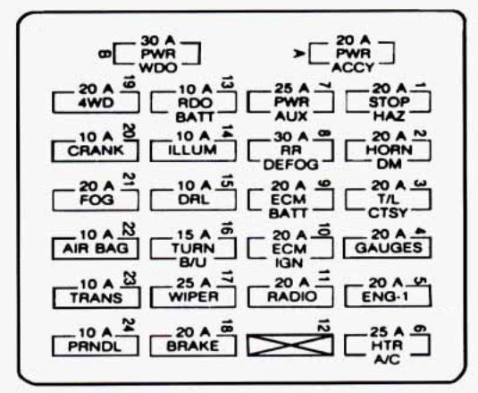
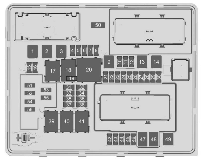
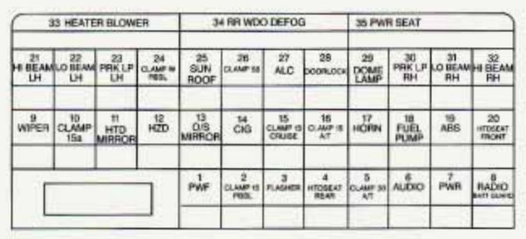
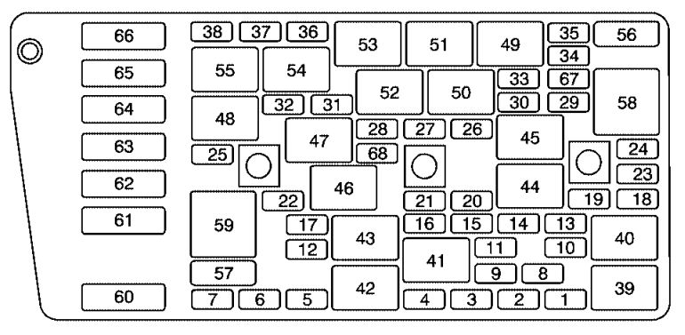
Instrument Panel Fuse Block
The fuse block is at the driver’s end of the instrument panel.
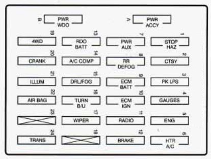
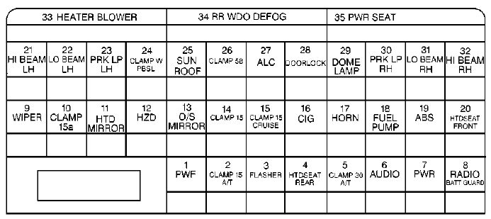
| Fuse/Circuit breaker | Circuit protected |
| A | Power Door Locks, Power Seat, Power Seat Lumbar, Remote Keyless Entry |
| B | Power Windows |
| 1 | Stoplamps, Hazard Lamps, Chime, Center High-Mounted Stoplamp Relay, Center High-Mounted Stoplamp |
| 2 | Dome Lamps, Cargo Lamps, Visor Vanity Mirror, Cigarette Lighter, Inside Rearview Mirror Lamp, Overhead Console Lamps, Glove Box Lamp, Horns, Horn Relay, IP Courtesy Lamps, Power Outside Rearview Mirror, Liftglass Release Motor, Illuminated Entry Module |
| 3 | Parking Lamps, License Plate Lamps, Electric Shift Transfer Case Module, Underhood Lamp, Rear Wiper, Ashtray Lamp, Door Switch Lamp |
| 4 | Alternator Field, A/C Compressor Relay, Cluster Chime Module, DRL Relay Coil, Four-Wheel-Drive Indicator Lamp, DRL Module, Rear Defog Timer, Transfer Case Control Module Ignition, SIR Redundant Ignition, RKE Ignition |
| 5 | Oxygen Sensor Heater, Exhaust Gas Recirculation, Cam Sensor, CANN. Purge, MAS |
| 6 | Blower Motor, Temperature Door Motor, HI Blower Relay Coil |
| 7 | Power Auxiliary Outlets, Assembly Line Diagnostic Link |
| 8 | Rear Window Defogger |
| 9 | PCM/VCM Battery, ABS Battery |
| 10 | PCM/VCM Ignition, Injectors, Crank Sensor, Coil Driver Module |
| 11 | Radio, Inside Rearview Mirror Map Lamp, Overhead Console Reading Lamps, Rear Wiper, Rear Washer, Overhead Console Display |
| 12 | DRAC, Anti-Lock Braking System, VCM IGN-3 |
| 13 | Clock, Radio, Battery, CD Player |
| 14 | A/C Compressor Battery Feed |
| 15 | Daytime Running Lamps, Fog Lamps, Fog Lamp Relay |
| 16 | Turn Signals and Back-up Lamps, Brake-Transmission Shift Interlock Solenoid |
| 17 | Windshield Washer, Windshield Wiper Motor |
| 19 | Electric Shift Transfer Case |
| 20 | Crank Signal, Air Bag System |
| 21 | Cluster Illumination, Radio Illumination, Heater Lamp, Four-Wheel-Drive Illumination, Chime Module, Fog Lamp Illumination, Rear Wiper Switch, Rear Defog Switch Illumination, Liftglass Release Switch Illurnination, Overhead Console Illumination |
| 22 | Air Bag System |
| 24 | PRNDL Power, 4L60E Automatic Transmission |
WARNING: Terminal and harness assignments for individual connectors will vary depending on vehicle equipment level, model, and market.