Ikco Dena – fuse box diagram
Year of production: 2015, 2016, 2017, 2018
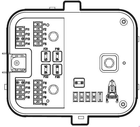
Fuse box on the dashboard
| Number | A | Description |
| F1 | 20 | Front seat electricity |
| F2 | 10 | Ignition switch 1,2 Brake switch power |
| F3 | 20 | Radio power |
| F4 | 10 | Lighter electricity |
| F5 | 30 | — |
| F6 | 20 | Vent fan |
| F7 | 10 | Starter |
| F8 | 5 | Reserve |
| F9 | 15 | CN electricity Immobilizer electricity |
| F10 | 15 | Right rear indicator Left rear fog lamp Right rear gear lamp Left brake lamp Plate lamp Right rear night warning lamp Rear window key regulator lamp RN electricity |
| F11 | 30 | Left rear indicator Right rear fog lamp Left rear gear lamp Right brake lamp Rear & front roof lamp controlled by doors Left rear night warning lamp RN electricity |
| F12 | 20 | Reserve |
| F13 | 30 | Rear window & mirror heater Left rear electrical window regulator Right rear electrical window regulator |
| F14 | 15 | Radio & memory of radio Diagnostic connector electricity |
| F15 | 5 | Front dashboard and central glove box lights Map reading, dashboard, make-up mirror and electric mirrors lights CCN power Back windows heater and mirror heater lights Flasher key light Central lock key light Boot opener key light FN front control power ICN power ICN memory power |
| F16 | 5 | Diagnosis connector power after switch Ignition switch 2,3 ABS power supply |
| F17 | 10 | Air bag |
| F21 | 20 | Electric Seat Supply |
| F22 | 10 | Main switch supply (position 2) air bag unit and air conditioning system |
| F23 | 10 | Main switch supply (position 1) lighter |
| F24 | 10 | Main switch supply – position 1 (motivation of heater relay • Radio, brake, light, front node, central node and instrument panel), Motivation of Glass Heater Relay |
| F25 | 10 | Radio permanent supply |
| F26 | 20 | Central node supply |
| F27 | 20 | Central node supply |
| F28 | 30 | Central node supply and motivation of rear door motive relay |
| F29 | 30 | Rear Lifting Window |
| F30 | 30 | Central node supply (Front lifting window) |
| F31 | 30 | Rear window heater |
| F32 | 30 | Heater fan supply |
| F33 | 30 | Engine ignition |
| F34 | 10 | Main switch supply (position 2) immobilizer, diagnostic connector, instrument panel, cooler gas pressure sensor, engine unit |
| F35 | 5 | Main switch supply (position 2), Anti-brake system (ABS) |
| F36 | 10 | Immobilizer permanent supply, diagnostic connector, instrument panel |
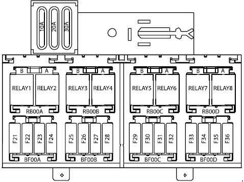
| Relay | ||
| R1 | — | |
| R2 | Trunk Lid Electric Actuator | |
| R3 | Mirrors and rear window heater | |
| R4 | Ventilation Fan Relay | |
| R5 | Rear Lifting Window (Left) | |
| R6 | Rear Lifting Window (Left) | |
| R7 | Rear Lifting Window (Right) | |
| R8 | Rear Lifting Window (Right) | |
Fuse Box
| Number | Ampere ratting [A] | Description |
| F1 | 30 | Wiper motor |
| F2 | 15 | AC compressor Wiper washer |
| F3 | 30 | Double relay 2 |
| F4 | 30 | Double relay 1 |
| F6 | 30 | ABS brake 2 |
| F7 | 30 | ABS brake 1 |
| F8 | 30 | Fan 1 |
| F9 | 20 | Right mirror heater Right front mirror indicator Right front window regulator Right front door functioning motor Right mirror motor Right folding mirror Right front door light Map reading light key Door feeding node |
| F10 | 20 | Left mirror heater Left front mirror indicator Left front window regulator Left front door functioning motor Left mirror motor Left folding mirror Left front door light Door feeding node |
| F11 | 30 | Horn |
| F12 | 10 | Door feeding node Alarm feeding |
| F14 | 10 | ECU |
| F16 | 15 | Right front fog lamp Left front fog lamp |
| F17 | 20 | Left front indicator Left main beam lamps Left Night warning lamp Right dipped head lamps |
| F18 | 20 | Right front indicator Right main beam lamps Right Night warning lamp Left dipped head lamps |
| F19 | 40 | Central node feeding 2 |
| F20 | 50 | Start feeding |
| F21 | 60 | Central node feeding 1 |
| F22 | 40 | Fan 2 |
Engine Compartment Fuse Box

| Number | Ampere ratting [A] | Description |
| 1 | 40 | Electric supply for ignition switch |
| 2 | 30 | Relay switch for fog lamp/horn |
| 3 | 40 | BCM Inside systems electric connection supply |
| 4 | 30 | BCM Inside systems electric connection supply |
| 5 | 40 | Fan (High speed) |
| 6 | 30 | Fan (Low speed) |
| 7 | 30 | Brake (ABS) |
| 8 | 40 | Brake (ABS) |
| 9 | — | Reserve |
| 10 | 20 | Front node supply |
| 11 | 15 | Front node supply |
| 12 | 30 | Front node supply windshield wiper and relay for windshield washer pump |
| 13 | — | Spare |
| 14 | 30 | Double relay supply |
| 15 | 10 | Fuel pump supply |
| 16 | 10 | Engine unit supply |
| 17 | — | Reserve |
| 18 | — | Reserve |
| 19 | — | Reserve |
| 20 | — | Reserve |
| Relay | ||
| Ra | Relay switch for engine control | |
| Rb | Relay switch for fuel pump | |
| R1 | Relay switch for fog lamp | |
| R2 | Relay switch for horn | |
| R3 | Relay switch for windshield wiper | |
| R4 | Relay switch for windshield wiper | |
| R5 | Relay switch for fan (high speed) | |
| R6 | Relay switch for fan (low speed) | |
| R7 | Relay for fan | |
| R8 | Relay for windshield washer pump | |
WARNING: Terminal and harness assignments for individual connectors will vary depending on vehicle equipment level, model, and market.