Isuzu Ascender (2008) – fuse box diagram
Year of production: 2008
Engine compartment
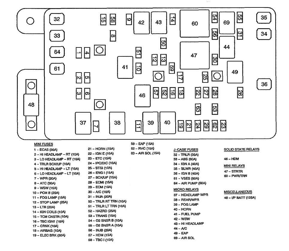
| No | Fuse name | A | Description |
| 1 | ECAS Fuse | 30 | Air Suspension Compressor Assembly |
| 2 | HI HEADLAMP-RT Fuse | 10 | Headlamp – High Beam – Right |
| 3 | LO HEADLAMP-RT Fuse | 10 | Head lamp – Low Beam – Right |
| 4 | TRLR BCK/UP Fuse | 10 | Trailer Connector |
| 5 | HI HEADLAMP-LT Fuse | 10 | Headlamp- High Beam – Left |
| 6 | LO HEADLAMP-LT Fuse | 10 | Headlamp – Low Beam – Left |
| 7 | WPR Fuse | 20 | HEADLAMP WPR Relay, REAR/WPR Relay |
| 8 | ATC Fuse | 30 | Transfer Case Encoder .Motor, Transfer Case Shift Control Module |
| 9 | WSW Fuse | 15 | WSW Relay |
| 10 | PCM B Fuse | 20 | FUEL PUMP Relay |
| 11 | FOG LAMP Fuse | 15 | FOG LAMP Relay |
| 12 | STOP LAMP Fuse | 25 | Stop Lamp Switch |
| 13 | LTR Fuse | 20 | Cigar Lighter, Data Link Connector (DLC) |
| 14 | IGN COILS Fuse | 10 | HI HEADLAMP Relay |
| 15 | TCM CNSTR Fuse | 10 | Evaporative Emission (EVAP) Canister Vent Solenoid, Transmission Control Module (TCM) |
| 16 | TBC IGN1 Fuse | 10 | Body Control Module (BCM) |
| 17 | CRNK Fuse | 10 | Engine Control Module (PCM) |
| 18 | AIR BAG Fuse | 10 | Inflatable Restraint Front Passenger Pressure System (PPS) Module, Inflatable Restraint Sensing and Diagnostic Module (SDM), Rollover Sensor |
| 19 | ELEC BRK Fuse | 30 | Trailer Brake Wiring |
| 21 | HORN Fuse | 15 | HORN Relay |
| 22 | IGN E Fuse | 10 | A/C Relay, Headlamp l eveling Actuators, Headlamp Switch, Inside Rearview Mirror, Instrument Panel Cluster (I PC), Park/Neutral Position (PNP) Switch, Stop Lamp Switch, Turn Signal/Multifunction Switch |
| 23 | ETC Fuse | 15 | IIEngine Control Module (ECM) |
| 24 | IPC/DIC Fuse | 10 | Instrument Panel Cluster (IPC) |
| 25 | BTSI Fuse | 10 | Automatic Transmission Shift Lock Actuator, Stop Lamp Switch |
| 26 | ENG I Fuse | 15 | Evaporative Emission (EVAP) Canister Purge Solenoid, Mass Air Flow (MAF)/Intake Air Temperature (IAT) Sensor, Valve Lifter Oil Manifold (VLOM) Assembly |
| 27 | BCK/UP Fuse | 15 | EAP Relay, Park/Neutral Position (PNP) Switch |
| 28 | ECMI Fuse | 15 | Engine Control Module (ECM) |
| 29 | ECM Fuse | 10 | Engine Control Module (ECM) |
| 30 | A/C Fuse | 10 | A/C Relay |
| 31 | INJA Fuse | 10 | odd Fuel Injectors, Odd Ignition Coils |
| 32 | TRLR Fuse | 30 | Trailer Connector |
| 33 | ABS Fuse | 60 | Electronic Brake Control Module (EBCM) |
| 34 | IGN A Fuse | 40 | Ignition Switch- ACCY/RUN/START, RUN, START BUS |
| 35 | BLWR Fuse | 40 | Blower Motor Control Module, Blower Motor Resistor Assembly |
| 36 | IGN B Fuse | 40 | Ignition Switch – ACCY/RUN, RUN/START BUS |
| 37 | HEADLAMP WPR Relay | — | Headlamp Washer Fluid Pump |
| 38 | REAR/WPR Relay | — | Rear Window Washer Fluid Pump |
| 39 | FOG LAMP Relay | — | Front Fog Lamps |
| 40 | HORN Relay | — | Horn Assembly |
| 41 | FUEL PUMP Relay | — | Fuel Pump and Sender Assembly |
| 42 | WSW Relay | — | Windshield Washer Fluid Pump |
| 43 | HI HEADLAMP Relay | — | HI HEADLAMP- LT Fuse, HI HEADLAMP-RT Fuse |
| 44 | A/C Relay | — | A/C Compressor Clutch Assembly |
| 45 | FAN Relay | — | Cooling Fan |
| 46 | HDM Relay | — | LO HEADLAMP- L T Fuse, LO HEADLAMP-RT Fuse |
| 47 | STRTR Relay | — | Starter |
| 48 | I/P BATT Fuse | 125 | Fuse Block- Rear – B+ Bus |
| 49 | EAP Relay | — | Electronic Adjustable Pedals (EAP) Switch |
| 50 | TRLR RT TRN Fuse | 10 | Trailer Connector |
| 51 | TRLR LT TRN Fuse |
10 | Trailer Connector |
| 52 | HAZRD Fuse | 25 | Turn Signal/Hazard Flasher Module |
| 53 | TRANS Fuse | 15 | Automatic Transmission, Transmission Control Module (TCM) |
| 54 | O2 SNSR B Fuse | 10 | Heated Oxygen Sensor (H02S) Bank 1/2 Sensor 2 |
| 55 | O2 SNSR B Fuse | 10 | Heated Oxygen Sensor (H02S) Bank 1/2 Sensor 1 |
| 56 | INJB Fuse | 20 | IIEven Fuel Injectors, Even Ignition Coils |
| 57 | HDM Fuse | 15 | HDM Relay |
| 58 | TBC I Fuse | 10 | Body Control Module (SCM), Theft Deterrent Alarm, Theft Deterrent Control Module |
| 59 | EAP Fuse | 15 | EAP Relay, Electronic Adjustable Pedals (EAP) Relay |
| 60 | PWR/TRN RELAY | — | ENGI Fuse, ETC Fuse, INJA Fuse, INJB Fuse, 02 SNSR A Fuse, 02 SNSR B Fuse |
| 61 | VSES Fuse | 60 | Eiectronic Brake Control Module (EBCM) |
| 62 | RVC Fuse | 15 | Regulated Voltage Control Module |
| 63 | AIR SOL Fuse | 15 | Secondary Air Injection (AIR) Pump Relay |
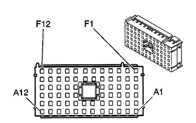
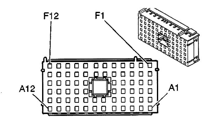
Underhood Fuse Block (Top View)
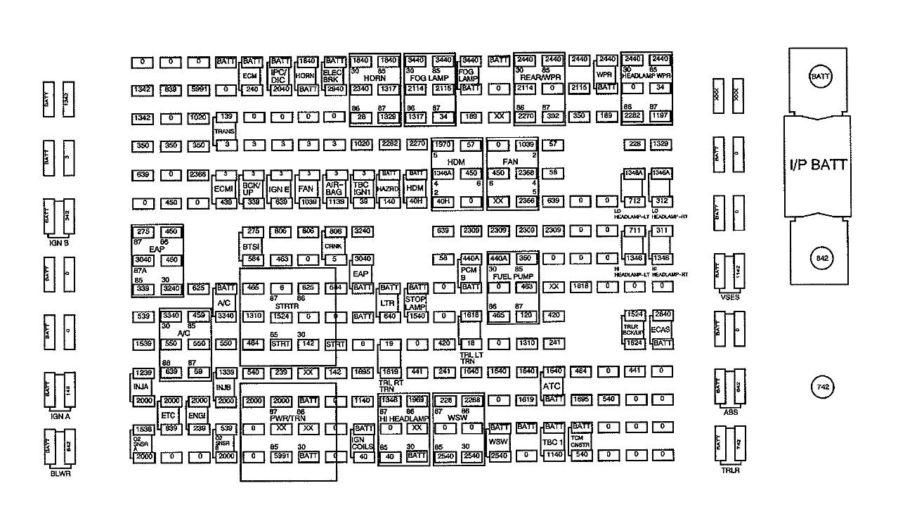
Underhood Fuse Block (Bottom View)
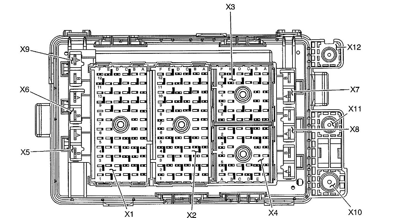
Underhood X1 Fuse block
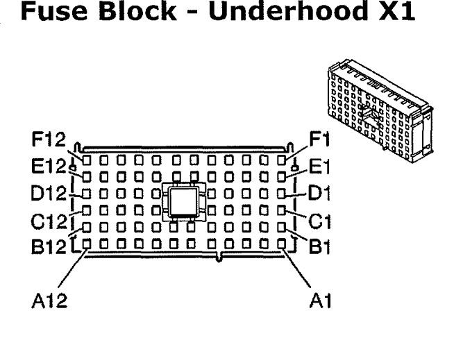
| Pin | Wire | Circuit | Function |
| A1 | — | — | — |
| A2 | — | — | — |
| A3 | — | — | — |
| A4 | — | — | — |
| A5 | 0.35 PK | 639 | lgnition 1 Voltage (M30) |
| A6 | 0.35 PU | 806 | Crank Voltage |
| A7 | 0.35 OG/BK | 463 | Requested Torque Signal |
| A8 | 5 PU | 6 | Starter Solenoid Crank Voltage |
| A9 | 0.8 GY | 1524 | Backup Lamp Signal (UY7) |
| A10 | 0.35 YE | 1737 | Neutral Safety Switch Park/Neutral Signal (M30) |
| A11 | 0.5 PK | 239 | Ignition 1 Voltage |
| 0.5 PK | 239 | Ignition 1 Voltage (6.0L) | |
| A12 | — | — | — |
| B1 | 0.35 OG | 240 | Battery Positive Voltage |
| B2 | — | — | — |
| B3 | — | — | — |
| B4 | — | — | — |
| B5 | 0.8 PK | 339 | Ignition 1 Voltage |
| B6 | 0.5 L-GN | 275 | Park Neutral Position Switch Pa rk Signal |
| B7 | — | — | — |
| B8 | 0.35 D-GN/WH | 465 | Fuel Pump Relay Control |
| B9 | 0.35WH | 1310 | EVAP Canister Vent Solenoid Control |
| B10 | 0.35 TN/8K | 464 | Delivered Torque Signal |
| B11 | 0.35 OG | 540 | Battery Positive Voltage |
| B12 | — | — | — |
| C1 | 0.8 OG | 3840 | Battery Posit ive Voltage |
| C2 | 0.5 PK | 139 | Ignition 1 Voltage |
| C3 | — | — | — |
| C4 | — | — | — |
| C5 | 0.5 PK | 439 | Ignition 1 Voltage |
| C8 | — | — | — |
| C9 | — | — | — |
| C10 | 2 BK | 550 | Ground |
| C11 | 0.8 PK | 1339 | Ignition 1 Voltage |
| C12 | — | — | — |
| D1 | 0.35 YE | 5991 | Powertrain Relay Coil Cont rol |
| D2 | — | — | — |
| D3 | 0.35 BK | 350 | Ground |
| D4 | 0.35 WH/BK | 2366 | Cooling Fan Clutch Control |
| D5 | — | — | — |
| D8 | 0.35 YE/BK | 625 | Starter Enable Relay Control |
| D9 | 0.35 D-GN/WH | 459 | A/C Compressor Clutch Relay Control |
| D10 | 0.8 BK | 550 | Ground |
| D11 | 0.35 D-GN | 59 | A/C Compressor Clutch Supply Voltage |
| D12 | — | — | — |
| E1 | 0.5 PK | 839 | Ignition 1 Voltage |
| E2 | — | — | — |
| E3 | — | — | — |
| E4 | — | — | — |
| E5 | — | — | — |
| E6 | 1 BK | 450 | Ground |
| E7 | 0.35 BK | 450 | Ground |
| 0.5 BK | 450 | Ground (M30 | |
| E8 | — | — | — |
| E9 | — | — | — |
| E10 | — | — | — |
| E11 | — | — | — |
| E12 | — | — | — |
| F1 | — | — | — |
| F2 | — | — | — |
| F3 | 1 BK | 350 | Ground |
| F4 | — | — | — |
| F5 | — | — | — |
| F6 | — | — | — |
| F7 | — | — | — |
| F8 | — | — | — |
| F9 | 0.5 PK | 539 | Ignition 1 Voltage |
| 0.5 PK | 539 | Ignition 1 Voltage | |
| F10 | 0.5 PK | 1539 | Ignition 1 Voltage |
| 0.5 PK | 1539 | Ignition 1 Voltage | |
| F11 | 0.8 PK | 1239 | Ignition 1 Voltage |
| 0.8 PK | 1239 | Ignition 1 Voltage | |
| F12 | — | — | — |
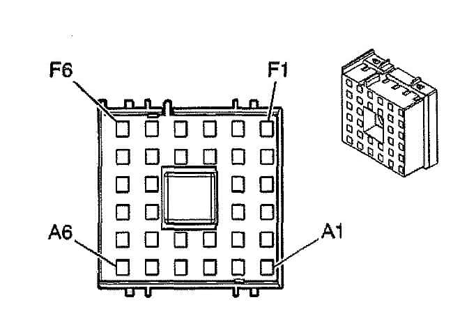
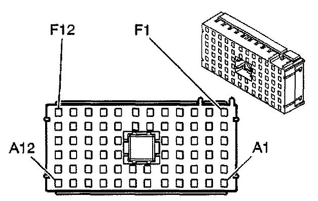
Underhood X2 Fuse block
| Pin | Wire | Circuit | Function |
| A1 | — | — | — |
| A2 | 0.5 D-GN | 189 | Headlamp Leveling Motor Supply Voltage (TR6) |
| A3 | 0.35 OG | 57 | Left Cornering Lamp Supply Voltage (Z88/Z89/W49) |
| A4 | — | — | — |
| A5 | 0.35WH/BK | 2366 | Cooling Fan Clutch Control ( 4.2L) |
| A6 | 0.35 BN | 2309 | Front Park Lamps Supply Voltage |
| A7 | 0.8 OG | 440 | Battery Positive Voltage ( 4.2L) |
| A8 | — | — | — |
| A9 | — | — | — |
| A10 | 0.8 YE | 18 | Left Rear Stop/Turn Lamp Supply Voltage (UY7) |
| A11 | 2 OG | 1640 | Battery Positive Voltage (NP4/NP8) |
| A12 | 0.35 OG | 2268 | Windshield Washer Relay Control |
| B1 | 0.35 D-BU | 2115 | Right Turn Signal Lamps Supply Voltage |
| B2 | — | — | — |
| B3 | 0.35 PK/WH | 1970 | Headlamp Low Beam Relay Control |
| B4 | — | — | — |
| B5 | — | — | — |
| B6 | 0.35 PK | 639 | Ignition 1 Voltage |
| B7 | 0.35 BK | 58 | Right Cornering Lamp Supply Voltage (Z88/Z89/W49) |
| B8 | — | — | — |
| B9 | — | — | — |
| B10 | 0.35 PU | 420 | TCC Brake Switch/Cruise Control Release Signal |
| B11 | 0.5 BN | 241 | Ignition 3 Voltage |
| B12 | — | — | — |
| C1 | 0.35 L-BU | 2114 | Left Turn Signal Lamps Supply Voltage |
| C2 | 0.35 D-GN/WH | 1317 | Front Fog Lamp Relay and Indicator Control (T96) |
| C3 | 0.35 L-GN | 2270 | Rear Window Washer Relay Control |
| C4 | — | — | — |
| C5 | — | — | — |
| C8 | — | — | — |
| C9 | 1 OG | 1540 | Battery Positive Voltage |
| C10 | 0.35 YE | 5991 | Powertrain Relay Coil Control ( 4.2L) |
| C11 | — | — | — |
| C12 | 0.35 BK/WH | 1969 | Headlamp High Beam Relay Control |
| D1 | 0.35 D-GN/WH | 1317 | Front Fog Lamp Relay and Indicator Control (T96) |
| D2 | — | — | — |
| D3 | 0.35WH | 2282 | Headlamp Washer Relay Control (CE4) |
| D4 | — | — | — |
| D5 | 2 OG | 140 | Battery Positive Voltage |
| D8 | — | — | — |
| D9 | 0.8 OG | 640 | Battery Positive Voltage |
| D10 | 0.8 D-GN | 19 | Right Rear Stop/Turn Lamp Supply Voltage (UY7) |
| D11 | — | — | — |
| D12 | — | — | — |
| E1 | 0.35 OG | 2340 | Battery Positive Voltage |
| E2 | 0.35 BK | 28 | Horn Relay Control |
| E3 | 0.35 PK | 1020 | Ignition 0 Voltage ( 4.2L) |
| E4 | — | — | — |
| E5 | 0.35 PK | 39 | Ignition 1 Voltage |
| E6 | 0.5 OG | 3240 | Battery Positive Voltage (JF4) |
| E7 | 0.5 OG | 3040 | Battery Positive Voltage (JF4) |
| E8 | — | — | — |
| E9 | — | — | — |
| E10 | 0.35 L-GN/BK | 584 | A/T Shift Lock Control Switch Supply Voltage ( 4.2L) |
| E11 | 0.5 BK/WH | 1695 | Axle Switch Signal (NP8) |
| E12 | 0.35 OG | 1140 | Battery Positive Voltage |
| 0.35 OG | 1140 | Battery Positive Voltage (BAE) | |
| F1 | 3 OG | 2940 | Battery Positive Voltage (UY7) |
| F2 | — | — | — |
| F3 | — | — | — |
| F4 | — | — | — |
| F5 | 0.35 YE | 1139 | Ignition 1 Voltage |
| F6 | 0.35 PU | 806 | Crank Voltage ( 4.2L) |
| F7 | 3 YE | 5 | Crank Voltage |
| F8 | 0.35 L-GN/BK | 584 | A/T Shift Lock Control Switch Supply Voltage (5.3L/6.0L) |
| 0.35 YE/BK | 625 | Starter Enable Relay Control ( 4. 2L) | |
| F9 | — | — | — |
| F10 | 0.35 D-GN | 1433 | PNP/Ciutch Start Switch Signal (4.2L) |
| 0.35 OG/BK | 1786 | Park/Neutral Signal (5.3L/6.0L) | |
| F11 | 3 RD | 142 | Battery Positive Voltage |
| F12 | o.35 D-GN/WH | 459 | A/C Compressor Clutch Relay Control (4. 2L) |
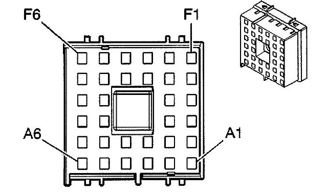
Underhood X3 Fuse block
| Pin | Wire | Circuit | Function |
| A1 | — | — | — |
| A2 | 0.5 PK | 739 | Ignition 1 Voltage ( 4.2L w/K18) |
| 0.35 PK | 739 | Ignition 1 Voltage (w/BAE) | |
| A3 | 3 OG | 2840 | Battery Positive Voltage (G67) |
| A4 | — | — | — |
| A5 | 0.35 OG | 540 | Battery Positive Voltage |
| A6 | — | — | — |
| B1 | — | — | — |
| B2 | — | — | — |
| B3 | — | — | — |
| B4 | 0.8 L-GN | 1624 | Trailer Backup Lamps Supply Voltage (UY7) |
| B5 | 0.35 BN | 441 | Ignition 3 Voltage |
| B6 | — | — | — |
| C1 | — | — | — |
| C2 | — | — | — |
| C5 | — | — | — |
| C6 | 0.35 OG | 540 | Battery Positive Voltage (5.3L) |
| D1 | — | — | — |
| D2 | 0.8 YE | 1618 | Trailer Left Rear Turn/Stop Lamp Supply Voltage (UY7) |
| D5 | 0.35 TN/BK | 464 | Delivered Torque Signal |
| D6 | 0.5 BK/WH | 1695 | Axle Switch Signal (NP8) |
| E1 | — | — | — |
| E2 | — | — | — |
| E3 | 0.35 PU | 420 | TCC Brake Switch Signal |
| E4 | 0.5 BN | 241 | Ignition 3 Voltage (NP8) |
| 0.5 BN | 241 | IIIgnition 3 Voltage (G67) | |
| E5 | 2 OG | 1640 | Battery Positive Voltage (NP8) |
| E6 | — | — | — |
| F1 | 0.5 BK | 350 | Ground |
| 0.5 BK | 350 | Ground (NP8) | |
| F2 | 0.35 OG/BK | 463 | Requested Torque Signal |
| F3 | 0.8 GY | 120 | Fuel Pump Supply Voltage |
| F4 | 0.35 WH | 1310 | EVAP Canister Vent Solenoid Control |
| F5 | — | — | — |
| F6 | 0.8 D-GN | 1617 | Trailer Right Rear Turn/Stop Lamp Supply Voltage (UY7) |
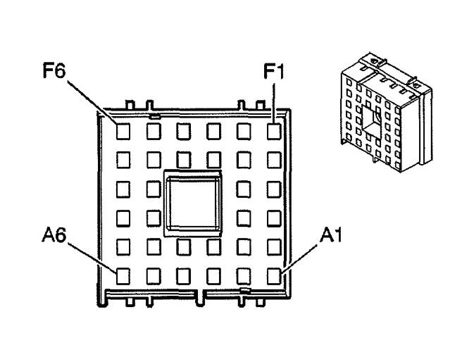
Underhood X4 Fuse block
| Pin | Wire | Circuit | Function |
| A1 | 0.35 BN | 2309 | Front Park Lamps Supply Voitage |
| 0.35 BN | 2309 | Front Park Lamps Supply Voltage (Except W49 w/o WX7) | |
| A2 | — | — | — |
| A3 | 0.35WH | 2368 | Cooling Fan Clutch Supply Voltage |
| A4 | — | — | — |
| A5 | — | — | — |
| A6 | 0.35 L-BU | 2114 | Left Turn Signal Lamps Supply Voltage |
| 0.35 L-BU | 2114 | Left Turn Signal Lamps Supply Voltage ( -WX7) | |
| B1 | 0.35 BN | 2309 | Front Park Lamps Supply Voltage |
| 0.35 BN | 2309 | Front Park Lamps Supply Voltage (Except W49 w/o WX7) | |
| B2 | 0.35 PK | 639 | Ignition 1 Voltage (TR6) |
| B3 | 0.35 BK | 639 | Ignition 1 Voltage (TR6) |
| B4 | 0.35 OG | 57 | Left Cornering Lamp Supply Voltage (Z88/W49) |
| B5 | 0.8 D-GN | 392 | Rear Window Washer Pump Control |
| B6 | — | — | — |
| C1 | — | — | — |
| C2 | — | — | — |
| C5 | 0.8 BK | 350 | Ground |
| C6 | 0.35 D-8U | 2115 | Right Turn Signal Lamps Supply Voltage |
| 0.35 D-8U | 2115 | Right Turn Signal Lamps Supply Voltage ( -WX7) | |
| D1 | — | — | — |
| D2 | — | — | — |
| D5 | 0.5 D-GN | 189 | Headlamp Leveling Motor Supply Voltage (TR6) |
| D6 | — | — | — |
| E1 | 0.35 D-GN/WH | 711 | Left Headlamp High Beam Supply Voltage |
| E2 | 0.35 YE | 712 | Left Headlamp Low Beam Supply Voltage |
| E3 | — | — | — |
| E4 | 0.5 RD | 228 | Windshield Washer Pump Control |
| E5 | — | — | — |
| E6 | — | — | — |
| F1 | 0.35 L-GN/BK | 311 | Right Headlamp High Beam Supply Voltage |
| F2 | 0.35 TN/WH | 312 | Right Headlamp Low Beam Supply Voltage |
| F3 | — | — | — |
| F4 | 0.5 D-GN | 1329 | Horn Fuse Supply Voltage |
| F5 | 0.8 PU | 1197 | Headlamp Washer Pump Control (CE4) |
| F6 | 0.8 PU | 34 | Fog Lamps Supply Voltage (T96) |
Underhood X5 Fuse block
| Pin | Wire | Circuit | Function |
| A | 3 RD/WH | 342 | Battery Positive Voltage |
| B | 3 PK | 3 | Ignition 1 Voltage |
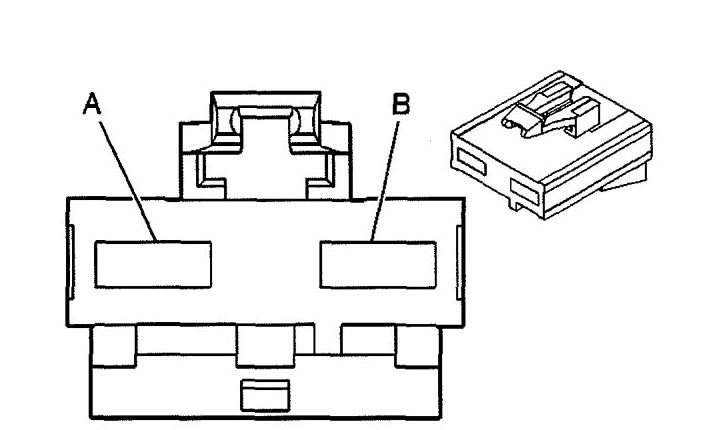
Underhood X7 Fuse block
| Pin | Wire | Circuit | Function |
| A | 5 RD | 1042 | Battery Positive Voltage ( 4.2L w/K18) |
| B | 5 RD | 642 | Battery Positive Voltage |
Underhood X8 Fuse block
| Pin | Wire | Circuit | Function |
| A | — | — | — |
| B | 5 RD | 4042 | Battery Positive Voltage |
Underhood X9 Fuse block
| Pin | Wire | Circuit | Function |
| A | 5 RD | 542 | Battery Positive Voltage (CJ3) |
| A | 3 RD | 542 | Battery Positive Voltage (CJ2) |
| B | — | — | — |
Underhood X10 Fuse block (Battery Positive Cable)
| Pin | Wire | Circuit | Function |
| 1 | 19 RD | 1 | Battery Positive Voltage |
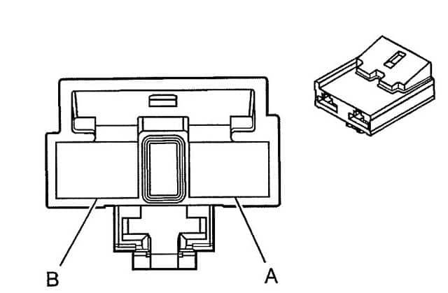
Rear Fuse Block
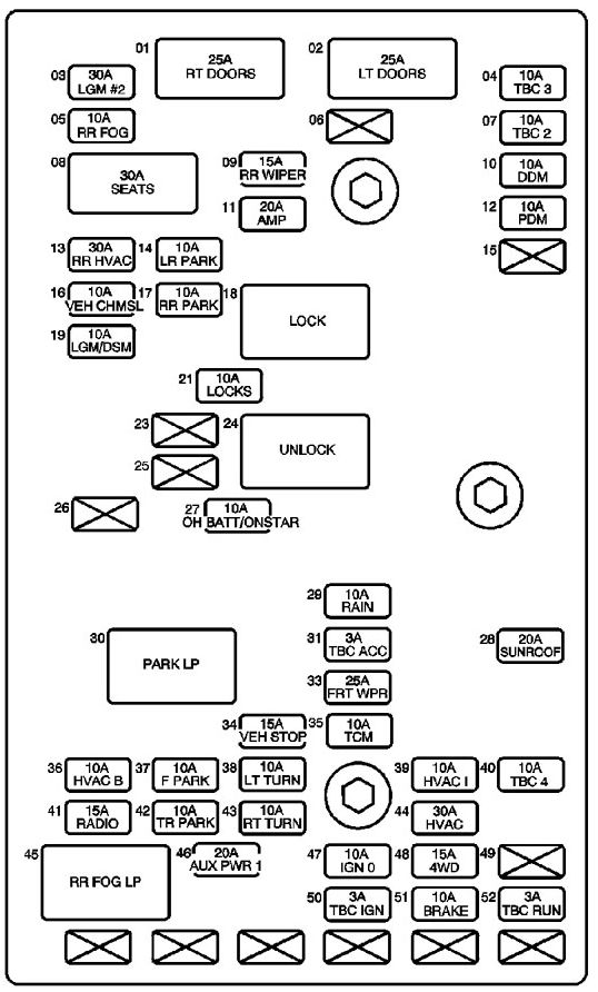
| No | Fuse name | A | Description |
| 1 | RT DOORS Circuit Breaker | 25 | Front Passenger Door Module (FPDM), Window Switch- RR |
| 2 | LT DOORS Circuit Breaker | 25 | Driver Door Module (DDM), Window Switch – LR |
| 3 | LGM #2 Fuse | 30 | Liftgate Module (LGM) |
| 4 | TBC 3 Fuse | 10 | Body Control Module (BCM) |
| 5 | RR FOG Fuse | 10 | Tail Lamp Circuit Board -Left |
| 6 | — | — | — |
| 7 | TBC 2 Fuse | 10 | Body Control Module (BCM) |
| 8 | SEATS Circuit Breaker | 30 | Lumbar Adjuster Switches, Memory Seat Module – Driver, Seat Adjuster Switches |
| 9 | RR WIPER Circuit Breaker | 15 | Rear Window Wiper Motor |
| 10 | DDM Fuse | 10 | Driver Door Module (DDM) |
| 11 | AMP Fuse | 20 | Audio Amplifier |
| 12 | PDM Fuse | 20 | Front Passenger Door Module (FPDM) |
| 13 | RR HVAC FUSE | 30 | — |
| 14 | LR PARK Fuse | 10 | License Lamps, Tail Lamp Circuit Board- Left |
| 15 | — | — | — |
| 16 | VEH CHMSL Fuse | 10 | Center High Mounted Stop Lamp (CHMSL) |
| 17 | RR PARK Fuse | 10 | Clearance Lamps, Tail Lamp Circuit Board – Right |
| 18 | LOCK Relay | — | Rear Door Latch Assemblies |
| 19 | LGM/DSM Fuse | 10 | Cobra Intrusion Sensor Module, Inclination Sensor, Liftgate Module (LGM), Memory Seat Module- Driver |
| 21 | LOCKS Fuse | 10 | LOCK Relay, UNLOCK Relay |
| 23 | — | — | — |
| 24 | UNLOCK Relay | — | Rear Door Latch Assemblies |
| 25 | — | — | — |
| 26 | — | — | — |
| 27 | OH BATT/ONSTAR Fuse | 10 | Digital Video Disc (DVD) Player, Garage Door Opener, Vehicle Communication Interface Module (CIM) |
| 28 | SUNROOF Fuse | 20 | Sunroof Motor |
| 29 | RAIN Fuse | 10 | — |
| 30 | PARK LP Relay | — | F PARK Fuse, LR PARK Fuse. RR PARK Fuse, TR PARK Fuse |
| 31 | TBC ACC Fuse | 3 | Body Control Module (BCM) |
| 32 | TBC 5 Fuse | 10 | Body Control Module (BCM) |
| 33 | FRT WPR Fuse | 25 | Windshield Wiper Motor |
| 34 | VEH STOP Fuse | 15 | Engine Control Module (ECM), Powertrain Control Module (PCM), Tail Lamp Circuit Board -Left/Right, Trailer Brake Wiring, Transmission Control Module (TCM) |
| 35 | TCM Fuse | 10 | Transmission Control Module (TCM) |
| 36 | HVAC B Fuse | 10 | HVAC Control Module, HVAC Control Module -Auxiliary |
| 37 | F PARK Fuse | 10 | Marker Lamps, Park Lamps, Park/Turn Signal Lamps, Turn Signal/Multifunction Switch |
| 38 | LT TURN Fuse | 10 | Driver Door Module (DDM), Instrument Panel Cluster (I PC), Marker Lamp, Park/Turn Signal Lamp- LF, Tail Lamp Circuit Board- Left, Turn Signal Lamp – LF |
| 39 | HVAC I Fuse | 10 | Air Temperature Actuators, Console Mode Actuator- Auxiliary, Defrost Actuator, HVAC Control Module, HVAC Control Module- Auxiliary, Mode Actuator, Recirculation Actuator, Steering Wheel Speed/Position Sensor, Turn Signal/Multifunction Switch |
| 40 | TBC 4 Fuse | 10 | Body Control Module (BCM) |
| 41 | RADIO Fuse | 15 | Digital Radio Receiver, Radio |
| 42 | TR PARK Fuse | 10 | Trailer Connector |
| 43 | RT TURN Fuse | 10 | Front Passenger Door Module (FPDM), Instrument Panel Cluster (I PC), Marker Lamp- RF, Park/Turn Signal Lamp- RF, Tail Lamp Circuit Board- Right, Turn Signal Lamp- RF |
| 44 | HVAC Fuse | 30 | HVAC Control Module |
| 45 | RR FOG LP Relay | — | RR FOG Fuse |
| 46 | AUX PWR 1 Fuse | 20 | Auxiliary Power Outlets |
| 47 | IGN 0 Fuse | 10 | Automatic Transmission, Automatic Transmission Shift Lock Actuator, Engine Control Module (ECM). Powertrain Control Module (PCM), Theft Deterrent Control Module |
| 48 | 4WD Fuse | 15 | Air Suspension Compressor Assembly, Auxiliary Water Pump Relay 1, Front Axle Actuator, Transfer Case Shift Control Switch |
| 49 | — | — | — |
| 50 | TBC IG Fuse | 3 | Body Control Module (BCM) |
| 51 | BRAKE Fuse | 10 | Electronic Brake Control Module (EBCM) |
| 52 | TBC RUN Fuse | 3 | Body Control Module (BCM) |
Rear fuse block (Top View)
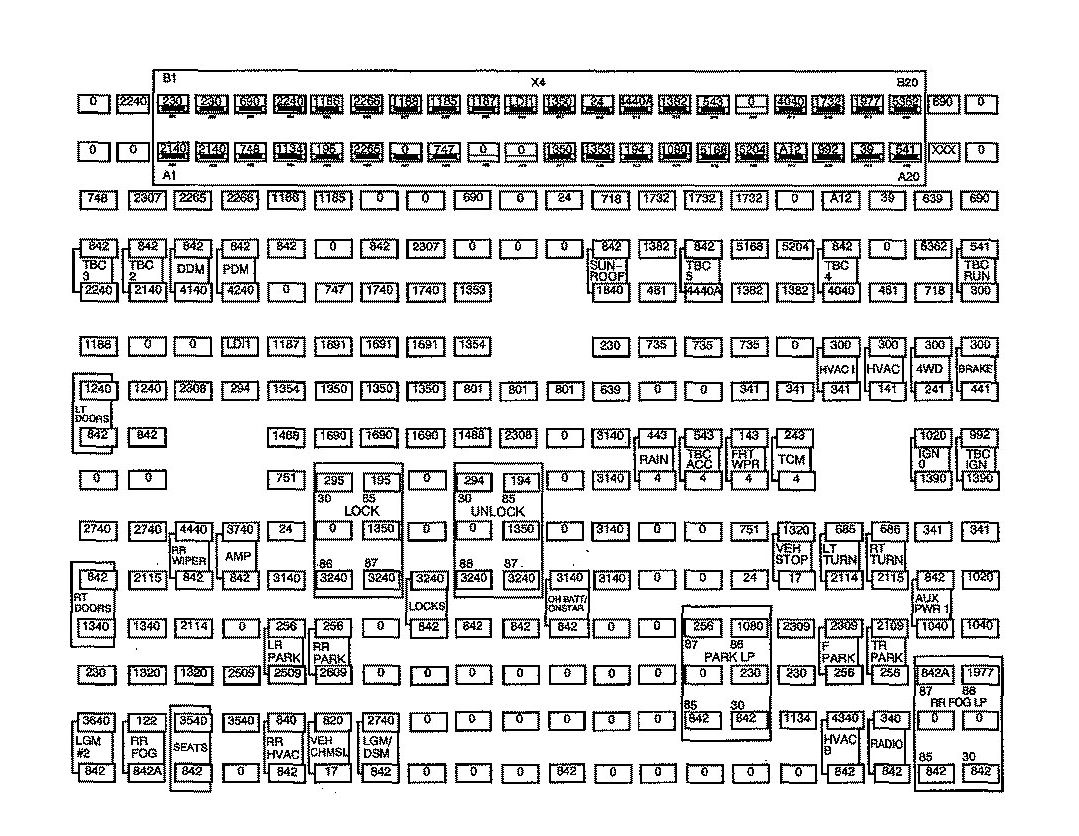
Rear fuse block (Bottom View)
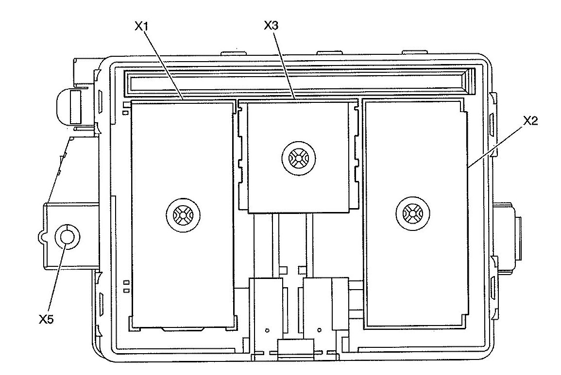
Rear fuse block X1
| Pin | Wire | Circuit | Function |
| A1 | — | — | — |
| A2 | 0.35 BN/WH | 230 | Instrument Panel Lamps Dimming Control |
| A3 | — | — | — |
| A4 | 0.35 L-GN | 24 | Backup Lamp Supply Voltage (Z88) |
| A5 | — | — | — |
| A6 | 3 BN | 4 | Accessory Voltage |
| A7 | 1 YE | 143 | Accessory Voltage |
| A8 | 0.35 BN | 341 | Ignition 3 Voltage |
| A9 | 0. 35 L-G N/BK | 735 | Ambient Air Temperature Sensor Signal (CJ3) |
| A10 | — | — | — |
| A11 | 0.35 TN/BK | 5168 | Power Sounder Enable Signal (BAE) |
| A12 | — | — | — |
| B1 | 0.35 L-BU | 1134 | Park Brake Switch Signal |
| B2 | 0.35 BN/WH | 230 | Instrument Panel Lamps Dimming Control |
| B3 | 0.35 BN | 2309 | Front Park Lamps Supply Voltage (Z88/Z89/W49) |
| B4 | 1 WH | 17 | Stop Lamp Switch Signal |
| B5 | 0.35 L-BU | 1320 | Stop Lamp Supply Voltage |
| 0.5 L-BU | 1320 | Stop Lamp Supply Voltage (UY7) | |
| B6 | — | — | — |
| B7 | 0.35 YE | 243 | Accessory Voltage (5.3L/6.0L) |
| B8 | 0.35 BN | 341 | Ignition 3 Voltage |
| B9 | — | — | — |
| B10 | 0.35 PU/WH | 1382 | LED Dimming Signal |
| 0.35 PU/WH | 1382 | LED Dimming Signal (NP8) | |
| B11 | 0.35 BN | 5204 | Intrusion Sensor Data Signal (8AE) |
| B12 | — | — | — |
| C1 | 0.35 OG | 4340 | Battery Positive Voltage |
| 0.35 OG | 4340 | Battery Positive Voltage (CJ2) | |
| C2 | — | — | — |
| C3 | 0.35 BN | 2309 | Front Park Lamps Supply Voltage |
| C4 | 0.35 L-BU | 2114 | Left Turn Signal Lamps Supply Voltage |
| C5 | 0.35 YE | 685 | Left Turn Signal Flasher Signal |
| C8 | 0.35 BN | 341 | Ignition 3 Voltage |
| C9 | — | — | — |
| C10 | — | — | — |
| C11 | — | — | — |
| C12 | — | — | — |
| D1 | 0.5 OG | 340 | Battery Positive Voltage |
| 0.5 OG | 340 | Battery Positive Voltage (U2K) | |
| D2 | — | — | — |
| D3 | 0.8 BN | 2109 | Trailer Park Lamps Supply Voltage (UY7) |
| D4 | 0.35 D-BU | 2115 | Right Turn Signal Lamps Supply Voltage |
| D5 | 0.35 TN | 686 | Right Turn Signal Flasher Signal |
| D8 | 3 BN | 141 | Ignition 3 Voltage (CJ3) |
| D9 | 3 OG | 300 | Ignition 3 Voltage |
| D10 | — | — | — |
| D11 | — | — | — |
| D12 | 0.35 PK | 39 | Ignition 1 Voltage |
| E1 | — | — | — |
| E2 | — | — | — |
| E3 | 1 OG | 1040 | Battery Positive Voltage |
| E4 | — | — | — |
| E5 | 0.35 BN | 341 | Ignition 3 Voltage |
| E6 | 3 WH | 1390 | Off/Run/Crank Voltage |
| E7 | 0.35 PK | 1020 | Ignition 0 Voltage |
| E8 | 0.5 BN | 241 | Ignition 3 Voltage |
| 0.5 BN | 241 | Ignition 3 Voltage (NP8/NR9) | |
| E9 | — | — | — |
| E10 | 0.35 BN | 718 | Low Reference (CJ3) |
| E11 | 0.35 L-BU | 5362 | Inclination Sensor Signal (BAE) |
| E12 | 0.35 PK | 639 | Ignition 1 Voltage |
| F1 | — | — | — |
| F2 | 0.35 YE | 1799 | Rear Fog Lamp Relay and Indicator Control (T79) |
| F3 | 1 OG | 1040 | Battery Positive Voltage |
| F4 | 0.35 PK | 1020 | Battery Positive Voltage (BAE) |
| F5 | 0.35 BN | 341 | Ignition 3 Voltage (JL4) |
| F6 | — | — | — |
| F7 | — | — | — |
| F8 | 0.35 BN | 441 | Ignition 3 Voltage |
| F9 | — | — | — |
| F10 | — | — | — |
| F11 | — | — | — |
| F12 | — | — | — |
Rear fuse block X2
| Pin | Wire | Circuit | Function |
| A1 | 2 OG | 3640 | Battery Positive Voltage |
| A2 | — | — | — |
| A3 | 2 OG | 1340 | Battery Positive Voltage |
| A4 | — | — | — |
| A5 | 0.35 OG | 2740 | Battery Positive Voltage (w/Memory) |
| A6 | — | — | — |
| A7 | — | — | — |
| A8 | 2 OG | 1240 | Battery Positive Voltage |
| A9 | 0.35 D-GN | 1188 | Power Window Switch Right Rear Down Signal |
| A10 | — | — | — |
| A11 | — | — | — |
| A12 | 0.35 L-GN/BK | 748 | Right Rear Door Ajar Switch Signal |
| B1 | 0.35 RD | 122 | Rear Fog Lamp Supply Voltage (T79) |
| B2 | 0.5 L-BU | 1320 | Stop Lamp Supply Voltage |
| B3 | 2 OG | 1340 | Battery Positive Voltage |
| B4 | 0.35 D-BU | 2115 | Right Turn Signal Lamps Supply Voltage |
| B5 | 0.35 OG | 2740 | Battery Positive Voltage |
| B6 | — | — | — |
| B7 | — | — | — |
| B8 | 2 OG | 1240 | Battery Positive Voltage |
| B9 | — | — | — |
| B10 | — | — | — |
| B11 | — | — | — |
| B12 | 0.35 D-BU | 2307 | Passenger Air Bag On Indicator Control (w/ALO) |
| C1 | 3 OG | 3540 | Battery Positive Voltage (AR9) |
| C2 | 0.5 L-BU | 1320 | Stop Lamp Supply Voltage |
| C3 | 0.35 L-BU | 2114 | Left Turn Signal Lamps Supply Voltage |
| C4 | — | — | — |
| C5 | 1 OG | 4440 | Battery Positive Voltage |
| C8 | 0.35 D-GN | 2308 | Passenger Air Bag Off Indicator Control (w/ ALO) |
| C9 | — | — | — |
| C10 | 0.35 OG | 4140 | Battery Positive Voltage |
| C11 | — | — | — |
| C12 | 0.35 L-BU | 2265 | Power Window Lockout Left Rear Signal |
| D1 | 3 OG | 3540 | Battery Positive Voltage (AR9) |
| D2 | 0.35 BN | 2509 | Left Rear Park Lamps Supply Voltage |
| D3 | — | — | — |
| D4 | — | — | — |
| D5 | 0.8 OG | 3740 | Battery Positive Voltage (UQA) |
| D8 | 0.35 TN | 294 | Door Lock Actuator Unlock Control |
| D9 | — | — | — |
| D10 | 0.35 OG | 4240 | Battery Positive Voltage |
| D11 | — | — | — |
| D12 | 0.35 L-GN | 2266 | Power Window Lockout Right Rear Signal |
| E1 | — | — | — |
| E2 | 0.35 BN | 2509 | Left Rear Park Lamps Supply Voltage |
| E3 | — | — | — |
| E4 | 0.35 OG | 3140 | Battery Positive Voltage (UEl) |
| E5 | 0.35 L-GN | 24 | Backup Lamp Supply Voltage (X88/W49/Z89) |
| E6 | — | — | — |
| E7 | — | — | — |
| E8 | — | — | — |
| E9 | 0.35 YE | 1187 | Power Window Switch Left Rear Down Signal |
| E10 | — | — | — |
| E11 | — | — | — |
| E12 | 0.35 GY/BK | 1186 | Power Window Switch Right Rear Up Signal |
| F1 | 0.35 YE | 820 | CHMSL Supply Voltage |
| F2 | 0.35 BN/WH | 2609 | Right Rear Park Lamps Supply Voltage |
| F3 | — | — | — |
| F4 | — | — | — |
| F5 | — | — | — |
| F6 | 0.35 GY | 295 | Door Lock Actuator Lock Control |
| F7 | — | — | — |
| F8 | 1 BK | 1350 | Ground |
| F9 | — | — | — |
| F10 | 0.35 L-BU/BK | 747 | Left Rear Door Ajar Switch Signal |
| F11 | — | — | — |
| F12 | 0.35WH | 1185 | Power Window Switch Left Rear Up Signal |
Rear fuse block X3
| Pin | Wire | Circuit | Function |
| A1 | — | — | — |
| A2 | 1 BK | 1350 | Ground |
| A3 | — | — | — |
| A4 | — | — | — |
| A5 | 0.35 D-BU | 2307 | Passenger Air Bag On Indicator Cont rol (w/ ALO) |
| A6 | — | — | — |
| B1 | — | — | — |
| B2 | — | — | — |
| B3 | — | — | — |
| B4 | 0.35 D-BU | 1353 | RAP Supply Voltage (CF5) |
| B5 | — | — | — |
| B6 | 0.35 GY/BK | 690 | Courtesy Lamp Low Control |
| C1 | 0.35 D-GN | 2308 | Passenger Air Bag On Indicato·r Control (w/ ALO) |
| C2 | — | — | — |
| C5 | — | — | — |
| C6 | — | — | — |
| D1 | — | — | — |
| D2 | — | — | — |
| D5 | — | — | — |
| D8 | 0.35 L-GN | 24 | Backup Lamp Supply Voltage (DD7 /DF5) |
| E1 | 0.35 OG | 3140 | Battery Positive Voltage |
| E2 | 0.35 PK | 639 | Ignition 1 Voltage (ALO/DD7 /DF5) |
| E3 | 0.35 BN/WH | 230 | Instrument Panel Lamps Dimming Control (UG1/CF5) |
| E4 | 1 OG | 1740 | Battery Positive Voltage (CFS) |
| E5 | — | — | — |
| E6 | 0 .35 BN | 718 | Low Reference (DD7 / DF5) |
| F1 | — | — | — |
| F2 | — | — | — |
| F3 | 0.35 L-GN/BK | 735 | Ambient Air Temperature Sensor Signal (DD7 /DF5) |
| F4 | — | — | — |
| F5 | — | — | — |
| F6 | 0.35 OG | 1732 | llcourtesy Lamps Supply Voltage |
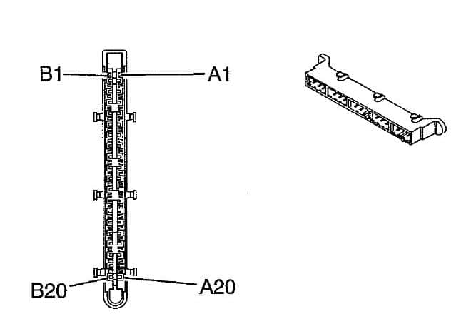
Rear fuse block X4
| Pin | Wire | Circuit | Function |
| A1 | — | 2140 | Battery Positive Voltage |
| A2 | — | 2140 | Battery Positive Voltage |
| A3 | — | 748 | Right Rear Door Ajar Switch Signal |
| A4 | — | 1134 | Park Brake Switch Signal |
| A5 | — | 195 | Door Lock Relay Control |
| A6 | — | 2265 | Power Window Lockout Left Rear Contro l |
| A7 | — | HD11 | — |
| A8 | — | 747 | Left Rear Door Ajar Switch Signal |
| A9 | — | LD14 | — |
| A10 | — | LD16 | — |
| A11 | — | 1350 | Ground |
| A12 | — | 1353 | RAP Supply Voltage |
| A13 | — | 194 | Door Unlock Relay Control |
| A14 | — | 1080 | — |
| A15 | — | LS05 | Power Sounder Enable Signal (BAE) |
| A16 | — | 1828 | Power Sounder Enable Signal (BAE) |
| A17 | — | A12 | — |
| A18 | — | 992 | Ignition o Voltage |
| A19 | — | 39 | Ignition 1 Voltage |
| A20 | — | 541 | Ignition 3 Voltage |
| B1 | — | 230 | — |
| B2 | — | 230 | — |
| B3 | — | 690 | Courtesy Lamp Supply Voltage |
| B4 | — | 2240 | Battery Positive Voltage |
| B5 | — | 1196 | Power Window Switch Right Rear Up Signal |
| B6 | — | 2266 | Power Window Lockout Right Rear Signal |
| B7 | — | 1188 | Power Window Switch Right Rear Down Signal |
| B8 | — | 1185 | Power Window Switch Left Rear Up Signal |
| B9 | — | 1187 | Power Window Switch Left Rear Down Signal |
| B10 | — | LD11 | — |
| B11 | — | 1350 | Ground |
| B12 | — | 24 | Backup Lamp Supply Voltage |
| B13 | — | 4440 | Battery Positive Voltage |
| B14 | — | 1382 | LED Dimming Signal |
| B15 | — | 543 | Accessory Voltage |
| B16 | — | HS02 | — |
| B17 | — | 4040 | Battery Positive Voltage |
| B18 | — | 1732 | Inadvertent Power Courtesy Lamps Supply Voltage |
| B19 | — | 1977 | Rear Fog Lamp Relay and Indicator Control (T79) |
| B20 | — | LS03 | Inclination Sensor Signal (BAE) |
WARNING: Terminal and harness assignments for individual connectors will vary depending on vehicle equipment level, model, and market.