Mercedes-Benz Sprinter (w906) (2006 – 2017) – fuse box diagram
Year of production: 2006, 2007, 2008, 2009, 2010, 2011, 2012, 2013, 2014, 2015, 2016, 2017
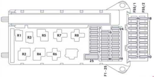
Main fuse box
Fuse box in the footwell on the left-hand side of the vehicle.
| № |
Consumer | A |
| 1 | Horn | 15 |
| 2 | ESTL (electric steering lock) ignition lock | 25 |
| 3 | Terminal 30 Z, vehicles with a gasoline engine/ ignition lock/instrument cluster | 10 |
| 4 | Light switch/switch unit on center console | 5 |
| 5 | Windshield wipers | 30 |
| 6 | Fuel pump Terminal 87 (5)1 |
15 10 |
| 7 | MRM (jacket tube module) | 5 |
| 8 | Terminal 87 (2) | 20 |
| 9 | Terminal 87 (1) Terminal 87 (3), vehicles with a gasoline engine Terminal 87 (3), vehicles with a diesel engine |
25 20 25 |
| 10 | Terminal 87 (4) | 10 |
| 11 | Terminal 15 R vehicle | 15 |
| 12 | Air bag control unit | 10 |
| 13 | Cigarette lighter/glove box lamp/radio/body manufacturer loading tailgate/PND (personal navigation device) power socket | 15 |
| 14 | Diagnostics connection/light switch/instrument cluster/deactivating reverse warning device/anti-theft protection with vehicle tracking | 5 |
| 15 | Headlamp range con- trol/front-compartment heating | 5 |
| 16 | Terminal 87 (1) Terminal 87 (3)1 |
10 |
| 17 | Air bag control unit | 10 |
| 18 | Terminal 15 vehicle/ brake light switch | 7.5 |
| 19 | Interior lighting | 7.5 |
| 20 | Front-passenger door power window switch/ terminal 30/2 SAM (signal acquisition and actuation module) | 25 |
| 21 | Engine control unit | 5 |
| 22 | Brake system (ABS) | 5 |
| 23 | Starter motor Terminal 87 (6)1 |
20 10 |
| 24 | Diesel engine, engine components/control unit, vehicles with a natural gas engine NGT2 | 10 |
| 25 | 12 V socket (center console) for tire sealant | 25 |
| Fuse block F55/1 | ||
| 1 | Driver’s door control unit | 25 |
| 2 | Diagnostics connection | 10 |
| 3 | Brake system (valves) | 25 |
| 4 | Brake system (delivery pump) | 40 |
| 5 | Terminal 87 (2a) engine M272, OM651 Terminal 87 (2a) engine OM642, OM6513 |
7.5 |
| 6 | Terminal 87 (1a) engine OM6426 Terminal 87 (1a) engine OM6516 Terminal 87 (3a) engine M272, M271, OM651 |
10 7.5 7.5 |
| 7 | Headlamp cleaning system | 30 |
| 8 | Anti-theft alarm system (ATA)/beacon/beacon with siren | 15 |
| 9 | Additional turn signal module | 10 |
| Fuse block F55/2 | ||
| 10 | Radio 1 DIN Radio 2 DIN |
15 20 |
| 11 | Mobile phone/tachograph/additional recorder4/navigation cradle6 | 7.5 |
| 12 | Front blower/auxiliary heating blower setting 1 | 30 |
| 13 | Auxiliary heating system digital timer/radio receiver/DIN slot basic wiring/FleetBoard/antitheft protection with vehicle tracking | 7.5 |
| 14 | Seat heating | 30 |
| 15 | Brake system control unit | 5 |
| 16 | Heating, rear compartment heating/ front-compartment air conditioning | 10 |
| 17 | Convenience lighting Motion detector Reading and cargo compartment lamp (courier vehicles) Cargo compartment lighting |
10 7.5 10 7.5 |
| 18 | Rear-compartment air-conditioning system | 7.5 |
| Relays |
||
| R1 | Horn relay | |
| R2 | Windshield wiper setting 1/2 relay | |
| R3 |
Fuel pump relay5
Starter relay, terminal 151
|
|
| R4 | Windshield wipers on/off relay | |
| R5 | Starter relay, terminal 50 | |
| R6 | Relay, terminal 15 R (normally open contact) | |
| R7 | Engine control unit relay, terminal 87 | |
| R8 | Relay, terminal 15 (reinforced relay) | |
| 1 – Vehicles with code MI6/MH3/XM0. 2 – Natural Gas Technology. 3 – NAFTA 4 – Latin America only. 5 – Not on vehicles with code MI6/MH3/XM0. 6 – Vehicles with code XM0. |
||
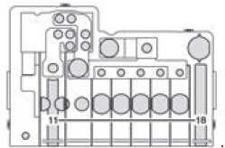
Pre-fuse box in the battery compartment in the footwell on the left-hand side of the vehicle F59

| № |
Consumer | A |
| 1 | Preglow relay Secondary air pump for vehicles with a gasoline engine |
80 40 |
| 2 | Air-conditioning system coolingfan – cab without partition and without rear-compartment air-conditioning system Air-conditioning system cooling fan – cab with partition and reinforced without rear-compartment air-conditioning system Air-conditioning system cooling fan – cab/ Electrical suction fan Starter relay, terminal 156 Starter relay unsupported6 |
60 40 40 25 25 |
| 3 | SAM (signal acquisition and actuation module)/SRB (fuse and relay module) | 80 |
| 4 | Auxiliary battery/ retarder Rear-compartment air-conditioning system |
150 80 |
| 5 | Terminal 30 pre-fuse boxes, SAM (signal acquisition and actuation module)/SRB (fuse and relay module) Terminal 30 electrical heater booster (PTC) input6 |
150 Bridge |
| 6 | Connection point on the base of the seat Pre-fuse box in the base of the seat6 |
Bridge Bridge |
| 7 | Rear-compartment air-conditioning system Electrical heater booster PTC |
80 150 |
| 6 – Vehicles with code XM0 | ||
Pre-fuse box at the base of the driver’s seat (only for auxiliary battery) F59/7

| № |
Consumer | A |
| 1 | Unassigned | – |
| 2 | SAM (signal acquisition and actuation module)/SRB (fuse and relay module) | 80 |
| 3 | Unassigned | – |
| 4 | Auxiliary battery input | 150 |
| 5 | Connection point on the base of the seat Pre-fuse box at the base of the seat | Bridge |
| 6 | SAM (signal acquisition and actuation module)/SRB (fuse and relay module), terminal 30 fuse box | 150 |
| 7 | Additional battery input Connection for socket fuse on vehicles with additional battery | Bridge |
| 8 | Retarder in combination with battery cutoff relay | 100 |
| 9 | Additional battery | 150 |
| 10 | Snowplow hydraulic pump Loading tailgate Tipper | 250 |
Pre-fuse box at the base of the driver’s seat (only for auxiliary battery) F59/8
| № |
Consumer | A |
| 11 | Terminal 30 starter battery input | Bridge |
| 12 | Unassigned | – |
| 13 | Electrical heater booster (PTC) Rear-compartment air-conditioning system |
150 80 |
| 14 | Air-conditioning system coolingfan – cab without partition and without rear-compartment air-conditioning system Air-conditioning system cooling fan – cab with partition and reinforced without rear-compartment air-conditioning system Air-conditioning system cooling fan – cab open vehicle model designation Electrical suction fan |
60 40 40 70 |
| 15 | Unassigned | |
| 16 | Retarder not in combination with battery cutoff relay Battery cutoff relay |
100 150 |
| 17 | Unassigned | – |
| 18 | Alternator | 300 |
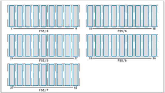
Fuse box under the left front seat
Fuse box on the outside of the seat base.
| № |
Consumer | A |
| Fuse block F55/3 | ||
| 1 | Mirror setting/rear window defroster | 5 |
| 2 | Rear window wiper | 30 |
| 3 | Auxiliary heating, digital timer/rear view camera/neutral gate switch, starting-off aid and allwheel drive/engine runon/DIN slot basic wiring (roof)/FleetBoard/anti-theft protection with vehicle tracking/emergency hammer lighting in the rear compartment | 5 |
| 4 | Tachograph/ADR working speed governor/ power take-off/AAG (trailer control unit) | 7.5 |
| 5 | ECO Start/control unit EGS (electronic gearbox control) |
5 10 |
| 6 | All-wheel drive control unit Auxiliary oil pump |
5 10 |
| 7 | ESM (electronic selector module) | 10 |
| 8 | Loading tailgate/tipper vehicle PARKTRONIC6 | 10 |
| 9 | Rear compartment air conditioning, compressor clutch, disengagea-ble reverse warning device | 7.5 |
| Fuse block F55/4 | ||
| 10 | Terminal 30, body/ equipment manufacturer | 25 |
| 11 | Terminal 15, body/ equipment manufacturer | 15 |
| 12 | D+, body/equipment manufacturer | 10 |
| 13 | Fuel pump FSCM (Fuel Sensing Control Module) Fuel pump relay1,3 |
20 15 |
| 14 | Trailer power socket | 20 |
| 15 | Trailer recognition unit | 25 |
| 16 | Tire pressure monitor PARKTRONIC7 | 7.5 |
| 17 | Programmable special module (PSM) | 25 |
| 18 | Programmable special module (PSM) | 25 |
| Fuse block F55/5 | ||
| 19 | Overhead control panel without ATA (Anti-Theft Alarm system) and without rain sensor Overhead control panel with ATA (Anti-Theft Alarm system) Overhead control panel with rain sensor |
5 25 25 |
| 20 | License plate lamp (courier vehicles)/perimeter lamp3/identification lighting3 | 7.5 |
| 21 | Terminal 30, body electrics (courier vehicles) Rear window defroster without ATA (Anti-Theft Alarm system) Rear window defroster with ATA (Anti-Theft Alarm system) |
15 30 15 |
| 22 | Rear window defroster 2 Vehicle socket (courier vehicles) |
15 20 |
| 23 | 12 V left rear socket, load/rear compartment Electric system: non-MB body |
15 10 |
| 24 | 12 V socket under the base of driver’s seat | 15 |
| 25 | 12 V right rear socket, load/rear compartment | 15 |
| 26 | Hot-water auxiliary heating | 25 |
| 27 | Electrical heater booster (PTC) Auxiliary warm-air heater |
25 20 |
| Fuse block F55/6 | ||
| 28 | SRB starter relay (fuse and relay module)3–6 Starterfor electrical supply support using the additional battery | 25 |
| 29 | Terminal 87 (7), gas system, vehicles with a natural gas engine (NGT)2 SCR8 control unit, vehicles with exhaust gas aftertreatment3 Terminal 30, all-wheel drive, control unit |
7.5 10 30 |
| 30 | Auxiliary heat exchanger fan Brake booster3 |
15 30 |
| 31 | Rear compartment heating blower Sliding door closing assistance, left Electric sliding door, left |
30 15 30 |
| 32 | SCR8 relay supply, vehicles with exhaust gas aftertreatment KEYLESS ENTRY |
5 10 |
| 33 | Electric sliding door, right Sliding door closing assistance, right ENR (level control) control unit Compressor air suspension |
30 15 30 30 |
| 34 | SCR8 heater 3 DEF (Diesel Exhaust Fluid) supply reservoir, vehicles with exhaust gas aftertreatment, 6 cyl. diesel9,3 SCR8 heater 1 DEF®, vehicles with exhaust gas aftertreatment diesel10 |
15 20 |
| 35 | SCR8 heater 2 hose, vehicles with exhaust gas aftertreatment, 6 cyl. diesel9,3 SCR8 heater 2 DEF, vehicles with exhaust gas aftertreatment diesel10 |
15 25 |
| 36 | SCR8 heater 1 delivery pump, vehicles with exhaust gas aftertreatment, 6 cyl. diesel9,3 SCR8 heater control 3 DEF, vehicles with exhaust gas aftertreatment diesel10 |
10 15 |
| Fuse block F55/7 | ||
| 37 | COLLISION PREVENTION ASSIST/FCW (Forward Collision Warning) Blind Spot Assist/BSM (Blind Spot Monitor) |
5 5 |
| 38 | Multifunction camera with Highbeam Assist With a warning when leaving a lane |
10 10 |
| 39 | Body electrics (courier vehicles) Rear-compartment air-conditioning system Roof ventilator Siren |
7.5 7.5 15 15 |
| 40 | Auxiliary battery charge current11 | 15 |
| 41 | SAM (signal acquisition and actuation module) auxiliary battery reference voltage11 | 7.5 |
| 42 | Rear-compartment air-conditioning system | 30 |
| 43 | Electrical step/sliding door, right | 10 |
| 44 | Electrical step/sliding door, left | 10 |
| 45 | Electrical step, control system and warning buzzer | 5 |
| 1 – Vehicles with code MI6/MH3/XM0. 2 – Natural Gas Technology. 3 – NAFTA 6 – Vehicles with code XM0. 7 – Pre-facelift vehicle. 8 – Selective Catalytic Reduction. 9 – Vehicles with code MH3. 10 – Not for vehicles with code MH3. 11 – Vehicles with auxiliary battery. |
||
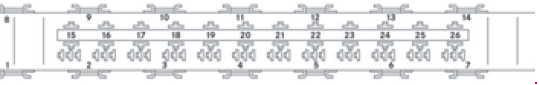
Relays in the seat base of the left front seat
| № |
Relays | Description |
| R1 | K6 | Starter relay, right-hand drive6 |
| R2 | K41 | Load relief relay, terminal 15 |
| R3 | K41/5 | Starter relay, terminal 15 |
| R4 | K64 K110 |
Secondary air injection/secondary air pump relay SCR relay8, vehicles with exhaust gas aftertreatment |
| R5 | K27 | Fuel pump relay |
| R6 | K23/1 | Blower relay, front, blower setting 1 |
| R7 | K41/2 | Load relief relay, terminal 15 R |
| R8 | K6/1 K6 |
Starter relay, additional battery Starter relay, left-hand drive6 |
| R9 | K13/5 | Rear window defroster relay 1 |
| R10 | K13/6 K51/15 |
Rear window defroster relay 2 with ATA (Anti-Theft Alarm system) Snow plow relay, low-beam headlamps, left |
| R11 | K117/3 K51/16 |
Electrical step relay 1, left Snow plow relay, low-beam headlamps, right |
| R12 | K117/4 K51/17 |
Electrical step relay 2, left Snow plow relay, high-beam headlamps, left |
| R13 | K41/3 K51/18 |
Load relief relay, terminal 15 (2) Snow plow relay, high-beam headlamps, right |
| R14 | K13/7 | Windshield heating relay 1 |
| R15 | K88 | Body manufacturer relay, terminal 15 |
| R16 | K88/1 | Body manufacturer relay, terminal 61 (D+) |
| R17 | K95 K93 | Loading tailgate basic wiring relay Comfort illumination relay |
| R18 | K2 | Headlamp cleaning system relay |
| R19 | K51/10 | Beacon with siren relay |
| R20 | K39/3 | ATA (anti-theft alarm system) relay, horn |
| R21 | K108 K116 K23/2 | Perimeter/identification lighting relay3 License plate lamp relay (courier vehicles) Blower relay, hot-air auxiliary heating, blower setting 1 |
| R22 | K23/3 | Blower relay, hot-air auxiliary heating, blower setting 2 |
| R23 | K39/1 K124/1 |
Siren relay Terminal 61 (D+) relay, anti-theft protection with vehicle tracking |
| R24 | K117/1 | Electrical step relay 1, right |
| R25 | K117/2 | Electrical step relay 2, right |
| R26 | K121 K124 |
Reverse warning device off relay Anti-theft protection with vehicle tracking relay |
| 3 – NAFTA 6 – Vehicles with code XM0. 8 – Selective Catalytic Reduction. |
||
Other relays
| № |
Relays | Description |
| – | K57 | Battery cutoff relay, left-hand-drive vehicle |
| – | K57/4 | Battery cutoff relay, right-hand-drive vehicle |
| – | K9 | Air-conditioning system relay, auxiliary fan (duo) |
| – | K9/2 | Air-conditioning system relay, auxiliary fan (mono) |
| – | K9/5 | Rear-compartment air conditioning relay, auxiliary fan |
| – | K120 | Auxiliary battery relay11 |
| 11 – Vehicles with auxiliary battery. | ||
WARNING: Terminal and harness assignments for individual connectors will vary depending on vehicle equipment level, model, and market.