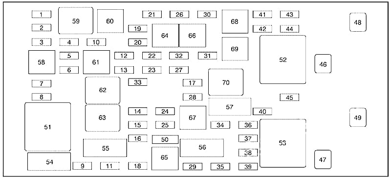
| No. |
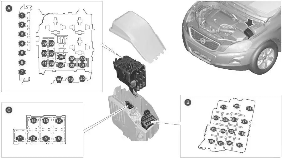
A |
Description |
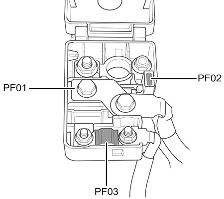
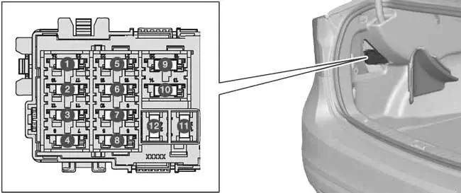
| 1 |
50 |
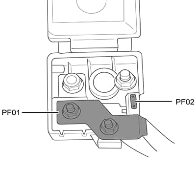
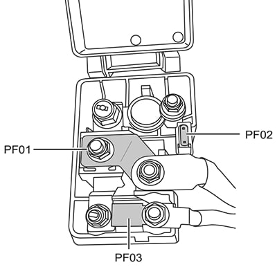
Primary fuse CEM KL30B |
| 2 |
50 |
Primary fuse CEM KL30A |
| 3 |
60 |
Primary fuse RJBA KL30 |
| 4 |
60 |
Primary fuse CJB KL30 |
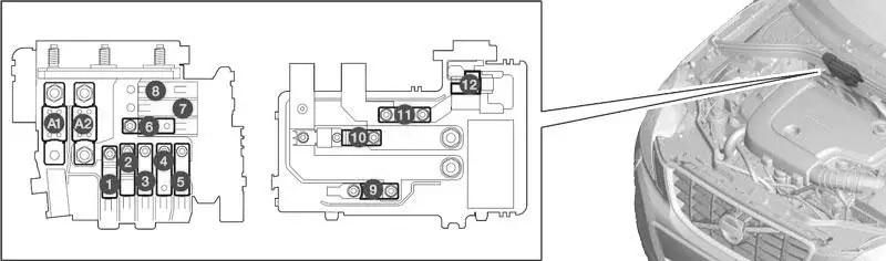
| 5 |
60 |
Primary fuse CJB 15E KL30 |
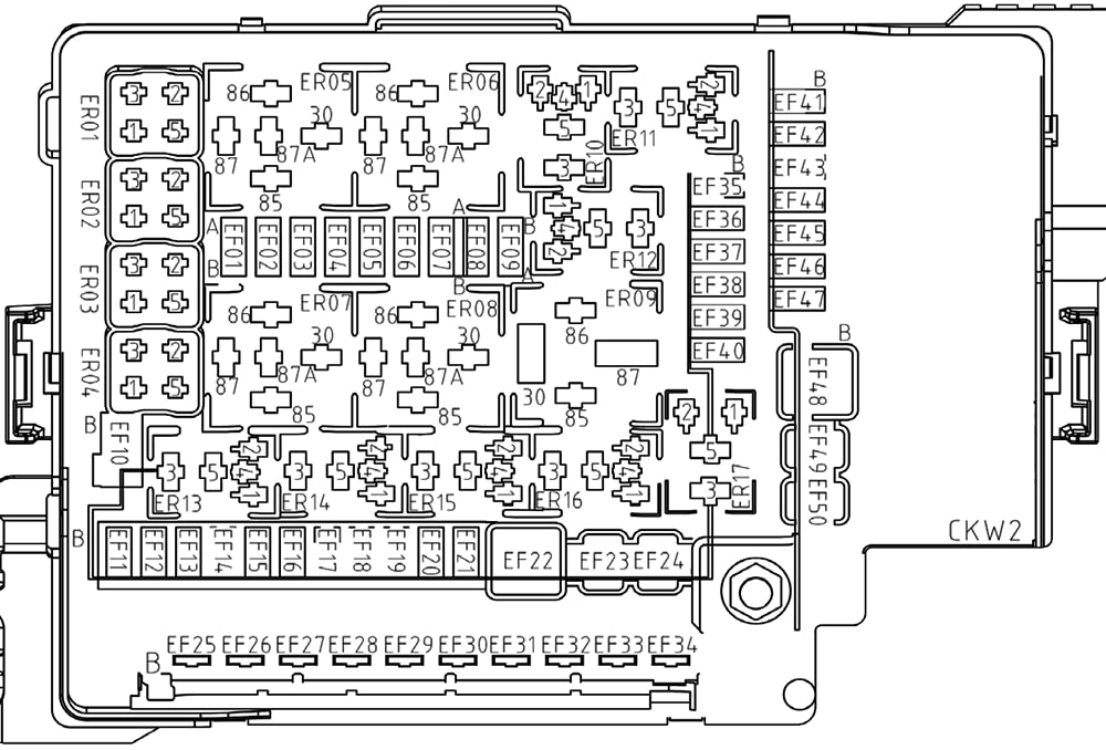
| 6 |
– |
– |
| 7 |
100 |
PTC Air preheater |
| 8 |
20 |
2011-2013: Headlamp washers |
| 40 |
2014-2018: Heated windscreen, lefthand side |
| 9 |
30 |
Windscreen wipers |
| 10 |
25 |
Parking heater |
| 11 |
40 |
Ventilation fan |
| 12 |
40 |
2014-2018: Heated windscreen, righthand side |
| 13 |
40 |
ABS pump |
| 14 |
20 |
ABS valves |
| 15 |
20 |
2014-2018: Headlamp washers |
| 16 |
10 |
Headlamp levelling, Active Xenon headlamps – ABL |
| 17 |
20 |
Primary fuse CEM |
| 18 |
5 |
ABS 15-feed |
| 19 |
5 |
Speed related power steering |
| 20 |
10 |
Engine control module, Transmission control module, Airbags |
| 21 |
10 |
Heated washer nozzles |
| 22 |
5 |
2011-2012: Vacuum pump 5-cyl Petrol Turbo and GTDI |
| 23 |
5 |
Headlamp control |
| 24 |
– |
– |
| 25 |
– |
– |
| 26 |
– |
– |
| 27 |
5 |
Relay, engine compartment box |
| 28 |
20 |
Auxiliary lamps |
| 29 |
15 |
Horn |
| 30 |
10 |
2011-2018: Engine Control Module (ECM) |
| 5 |
2016-2018, 4-cyl.: Engine Control Module (ECM) |
| 31 |
15 |
Transmission control module |
| 32 |
15 |
2011-2016: Compressor A/C,
2012-2018, diesel: Supporting coolant pump |
| 33 |
5 |
Relay coils |
| 34 |
30 |
2011-2016: Starter motor relay |
| 35 |
10 |
Ignition coils (4-cyl. petrol), Glow control module (5-cyl. diesel) |
| 20 |
Engine control module (4-cyl.), Ignition coils (5, 6 -cyl. petrol), Capacitor (6-cyl.) |
| 36 |
10 |
2011-2013: Engine control module (petrol)
2014-2015: Engine control module (petrol except 4-cyl. 2.0 l (does not apply to the B4204T7 engine))
2016: Engine control module (5, 6-cyl. petrol) |
| 15 |
2011-2013: Engine control module (diesel)
2014-2015: Engine control module (1.6 l diesel, 5-cyl. diesel)
2016-2018: Engine control module (5-cyl. diesel) |
| 20 |
2014-2015: Engine control module (4-cyl. 2.0 l (however, does apply to the B4204T7 engine))
2016-2018: Engine control module (4-cyl.) |
| 37 |
15 |
2011: Mass air flow sensor, valves (5-cyl diesel)
2012: Mass air flow sensor (5, 6-cyl.), Control valves (5-cyl. diesel), Injectors (5, 6-cyl. petrol), Engine control module (6-cyl.)
2013-2016: Mass air flow sensor (5-cyl. diesel, 6-cyl.); Control valves (5-cyl. diesel); Injectors (5, 6-cyl. petrol); Engine control module (5-cyl. petrol, 6-cyl.)
2017-2018: Mass airflow meter (5-cyl. diesel); Control valves (5-cyl. diesel) |
| 10 |
2012-2013: Valves (1.6 l petrol), Mass air flow sensor (1.6 l petrol), Mass air flow sensor (D4162T), Control valve, fuel flow (D4162T)
2014: Valves (1.6 l petrol); mass air flow sensor (1.6 l, 4-cyl. 2.0 l (does not apply to the B4204T7 engine.)); Thermostat (4-cyl. 2.0 l petrol (does not apply to the B4204T7 engine.)); EVAP valve (4-cyl. 2.0 l petrol (does not apply to the B4204T7 engine.)); Cooling valve for climate control system (4-cyl. 2.0 l diesel); Cooling pump for EGR (4-cyl. 2.0 l diesel) Mass air flow sensor (engine D4162T); Control valve, fuel flow (engine D4162T)
2015: Valves (1.6 l petrol); mass air flow sensor (1.6 l, 4-cyl. 2.0 l (does not apply to the B4204T7 engine)); Thermostat (4-cyl. 2.0 l petrol (does not apply to the B4204T7 engine)); EVAP valve (4-cyl. 2.0 l petrol (does not apply to the B4204T7 engine)); Cooling pump for EGR (4-cyl. 2.0 l diesel), Regulator valve, fuel flow (engine D4162T)
2016-2018: Mass air flow sensor (4-cyl.); Thermostat(4-cyl. petrol); EVAP valve (4-cyl. petrol); Cooling pump for EGR (4-cyl. diesel) |
| 38 |
10 |
2011: Engine valves
2012: Compressor A/C (5, 6-cyl.), Engine valves, Engine control module (6-cyl.) Solenoids (6-cyl. without turbo), Actuator motors, intake manifold (6-cyl. without turbo), Mass air flow sensor (4-cyl. 2.0 l petrol), Oil level sensor (5-cyl. diesel), Coolant pump (D4162T)
2013: Solenoid clutch A/C (5, 6-cyl.); Valves, Engine control module (6-cyl.) Solenoids (6-cyl. without turbo); Actuator motors, intake manifold (6-cyl. without turbo); Mass air flow sensor (4-cyl. 2.0 l petrol, 5-cyl. petrol); Oil level sensor (5-cyl. diesel), Coolant pump (D4162T)
2014-2015: Solenoid clutch A/C (5, 6-cyl.); Valves (1.6 l, engine B4204T7; 5-cyl., 6-cyl.); Engine control module (6- cyl.); Solenoids (6-cyl. without turbo); Actuator motors, intake manifold (6-cyl. without turbo); Mass air flow sensor (engine B4204T7; 5-cyl. petrol); Oil level sensor (5-cyl. diesel)
2016: Solenoid clutch A/C (5, 6-cyl.); Valves (5, 6-cyl.); Engine control module (6-cyl.); Mass air flow sensor (5- cyl. petrol); Oil level sensor
2017-2018: Solenoid clutch A/C (5-cyl. diesel); Valves (5-cyl. diesel); Oil level sensor |
| 15 |
2014-2015: Valves (4-cyl. 2.0 l (does not apply to the B4204T7 engine)); Oil pump (4-cyl. 2.0 l petrol (does not apply to the B4204T7 engine)); Lambdasond, centre (4-cyl. 2.0 l petrol (does not apply to the B4204T7 engine)); Lambda-sond, rear (4-cyl. 2.0 l diesel)
2016-2018: Valves (4-cyl.); Oil pump (4-cyl. petrol); Lambda-sond, centre (4-cyl. petrol); Lambdasond, rear (4-cyl. diesel) |
| 39 |
15 |
2011: EVAP, Lambda-sond, Injection (petrol)
2012-2013: EVAP valve (5, 6-cyl. petrol), Lambda-sonds (5, 6-cyl. petrol)
2014-2015: Lambda-sond, front (4-cyl. 2.0 l (does not apply to the B4204T7 engine)); Lambda-sond, rear (4- cyl. 2.0 l petrol (does not apply to the B4204T7 engine)); EVAP valve (5, 6-cyl. petrol); Lambdasonds (5, 6-cyl. petrol)
2016: Lambda-sond, front (4-cyl.); Lambda-sond, rear (4-cyl. petrol), EVAP valve (5, 6-cyl. petrol); Lambda-sonds (5, 6-cyl.); Control module radiator roller cover (5-cyl. diesel)
2017-2018: Lambda-sond, front (4-cyl.); Lambda-sond, rear (4-cyl. petrol) Lambda-sonds (5-cyl. diesel); Control module, radiator roller cover (5-cyl. diesel) |
| 10 |
2011: Lambda-sond (4-cyl. petrol, 5-cyl. diesel)
2012-2013: Lambda-sonds (4-cyl. petrol), Lambda-sond (diesel), Control module, radiator roller cover (manual 5-cyl. 2.0 l diesel)
2014-2015: Lambda-sonds (1.6 l petrol, engine B4204T7); Lambdasond (5-cyl. diesel); Control module, radiator roller cover (1.6 l diesel, 5-cyl. diesel) |
| 40 |
20 |
2011: Vacuum pump, crankcase valve (5-cyl. turbo, 2.0 GTDI) Diesel filter heater
2012: Vacuum pump (5-cyl. petrol), Crankcase ventilation heater (5-cyl. petrol), Diesel filter heater
2013-2018: Diesel filter heater |
| 10 |
2012: Coolant pump (1.6 l petrol Start/Stop)
2013: Coolant pump (1.6 l petrol Start/Stop, 5-cyl. petrol Start/Stop); Crankcase ventilation heater (5-cyl. Petrol); Oil pump automatic gearbox (5-cyl. petrol Start/Stop)
2014: Coolant pump (1.6 l petrol Start/Stop); Crankcase ventilation heater (5-cyl. petrol); Oil pump automatic gearbox(5-cyl. petrol Start/Stop)
2015: Coolant pump (1.6 l petrol Start/Stop) Coolant pump (5-cyl. petrol); Crankcase ventilation heater (5-cyl. petrol); Oil pump automatic gearbox (5-cyl. petrol Start/Stop)
2016: Coolant pump (5-cyl. petrol); Crankcase ventilation heater (5-cyl. petrol); Oil pump automatic gearbox (5-cyl. petrol Start/Stop) |
| 15 |
2014-2015: Ignition coils (4-cyl. 2.0 l petrol (does not apply to the B4204T7 engine))
2016-2018: Ignition coils (4-cyl. petrol) |
| 41 |
5 |
2011: Crankcase ventilation heater (5-cyl. diesel)
2013-2016: Control module, radiator roller cover (5-cyl. petrol) |
| 10 |
2012: Crankcase ventilation heater (5-cyl. diesel)
2013-2018: Crankcase ventilation heater (5-cyl. diesel); Oil pump automatic gearbox (5-cyl. diesel Start/Stop) |
| 15 |
2014: Solenoid clutch A/C (4-cyl. 2.0 l (does not apply to the B4204T7 engine)); Glow control module (4-cyl. 2.0 l diesel); Oil pump (4-cyl. 2.0 l diesel)
2015: Solenoid clutch A/C (4-cyl. 2.0 l diesel); Glow control module (4-cyl. 2.0 l diesel); Oil pump (4-cyl. 2.0 l diesel) |
| 7,5 |
2015: Solenoid clutch A/C (4-cyl. 2.0 l petrol (does not apply to the B4204T7 engine))
2016-2018: Solenoid clutch A/C (4-cyl.); Glow control module (4-cyl. diesel); Oil pump (4-cyl. diesel) |
| 42 |
70 |
2011: Glow plugs (5-cyl. diesel)
2012-2018: Glow plugs (diesel) |
| 50 |
2014-2015: Coolant pump (4-cyl. 2.0 l petrol (does not apply to the B4204T7 engine))
2016-2018: Coolant pump (4-cyl. petrol) |
| 43 |
60 |
2011-2012: Cooling fan (4 – 5-cyl. petrol)
2013: Cooling fan (4-cyl., 5-cyl. petrol)
2014-2015: Cooling fan (1.6 l, 4-cyl. 2.0 l petrol, 5-cyl. petrol)
2016: Cooling fan (4 – 5-cyl. petrol)
2017-2018: Cooling fan (petrol) |
| 80 |
2011-2012: Cooling fan (6-cyl. petrol), (5- cyl. diesel)
2013: Cooling fan (6-cyl., 5-cyl. diesel)
2014-2015: Cooling fan (6-cyl., 4-cyl. 2.0 l diesel, 5-cyl. diesel)
2016: Cooling fan (6-cyl., 4, 5-cyl. diesel)
2017-2018: Cooling fan (petrol, depending on cooling fan variant.), Cooling fan (diesel) |
| 44 |
80 |
2011: Electro-hydraulic power steering (1.6D) |
| 100 |
2011: Electro-hydraulic power steering (other)
2012-2013: Electro-hydraulic power steering
2014-2018: Power steering |