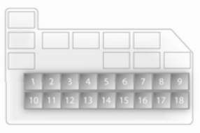
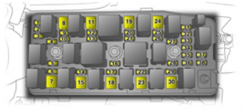
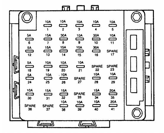
Opel Agila mk2 (2010) – fuse box diagram

Opel Agila mk2 (2010) – fuse box diagram

Year of production: 2010

Engine compartment fuse box

Opel Agila mk2 - bezpieczniki - komora silnika (silnik benzynowy)
Opel Agila mk2 – fuse box – engine compartment
Number Circuit
1 Heater fan
2 Fuel injection
3 Air conditioning compressor
4 Automatic transmission
5 Brake light switch
6 ABS, ESP
7 Starter motor
8
9 Power steering control module
10 Ignition switch
11 Radiator fan
12
13 ABS, ESP
14
15 Engine electrics
16 Front fog lights
17 Headlight (left)
18 Headlight (right)

Instrument panel fuse box

Opel Agila mk2 - bezpieczniki - deska rozdzielcza
Opel Agila mk2 – fuse box – instrument panel
Number Circuit
1
2 Ignition coils
3 Reversing light
4 Instrument cluster
5 Power outlet, cigarette lighter, power exterior mirror
6 Infotainment system
7 Power windows
8 Wipers/washers
9 Power steering
10 Airbag system
11 ABS, ESP
12 Tail light
13 Stop-start system
14 Door lock
15
16 Starter motor
17
18 Heater fan
19 Rear fog light
20 Infotainment system
21 Heated rear window
22 Horn, hazard warning
23 Stop-start system
24 Power window timer

WARNING: Terminal and harness assignments for individual connectors will vary depending on vehicle equipment level, model, and market.

Opel Antara (from 2011) – fuse box diagram

Opel Antara (from 2011) – fuse box

Years of production: 2011, 2012, 2013, 2014, 2015, 2016

Fuse box in engine compartment

Opel Antara (2011) - bezpieczniki - komora silnika
Opel Antara (2011) – fuse box – engine compartment
Fuse Circuit
ABS Anti-lock Brake System
A/C Climate control, air conditioning system
BATT1 Instrument panel fuse box
BATT2 Instrument panel fuse box
BATT3 Instrument panel fuse box
BCM Body Control Module
ECM Engine Control Module
ECM PWR TRN Engine Control Module, Powertrain
ENG SNSR Engine sensors
EPB Electrical parking brake
FAN1 Cooling fan
FAN3 Cooling fan
FRT FOG Front fog lights
FRT WPR Front wiper
FUEL/VAC Fuel pump, vacuum pump
HDLP WASHER Headlight washer
HI BEAM LH High beam (lefthand)
HI BEAM RH High beam (righthand)
HORN Horn
HTD WASH/MIR Heated washer fluid, heated exterior mirrors
IGN COIL A Ignition coil
IGN COIL B Ignition coil
LO BEAM LH Low beam (lefthand)
LO BEAM RH Low beam (righthand)
PRK LP LH Parking light (lefthand)
PRK LP RH Parking light (righthand)
PWM FAN Pulse width modulation fan
REAR DEFOG Heated rear window
REAR WPR Rear wiper
SPARE
DTOP LAMP Brake lights
STRTR Starter
TCM Transmission Control Module
TRLP PRL LP Trailer parking lights


Instrument panel fuse box

Opel Antara (2011) - bezpieczniki - deska rozdzielcza
Opel Antara (2011) – fuse box- instrument panel
Fuse Circuit
AMP Amplifier
APO JACK (CONSOLE) Power outlet (centre console)
APO JACK (REAR CARGO) Power outlet (load compartment)
AWD/VENT All-wheel drive, ventilation
BCM (CTSY) Courtesy lights
BCM (DIMMER) Instrument illumination
BCM (INT LIGHT TRLR FOG) Interior lights, trailer fog light
BCM (PRK/TRN) Parking lights, turn signals
BCM (STOP) Brake lights
BCM (TRN SIG) Turn signals
BCM (VBATT) Battery voltage
CIGAR Cigarette lighter
CIM Communications Integration Module
CLSTR Instrument cluster
DRL Daytime running lights
DR/LCK Driver door lock
DRVR PWR SEAT Driver power seat
DRV/PWR WNDW Driver power window
F/DOOR LOCK Fuel filler flap
FRT WSR Front washer
FSCM Fuel system
FSCM/VENT Fuel system, vent solenoid
HEATING MAT SW Heating mat switch
HTD SEAT PWR Seat heating
HVAC BLWR Climate control, air conditioning fan
IPC Instrument panel cluster
ISRVM/RCM Interior mirror, remote compass module
KEY CAPTURE Key capture
L/GATE Tailgate
LOGISTIC MODE Logistic mode
OSRVM Exterior mirrors
PASS PWR WNDW Passenger power window
PWR DIODE Power diode
PWR MODING Power moding
RADIO Radio
RR FOG Heated rear window
RUN 2 Power battery key on run
RUN/CRNK Run crank
SDM (BATT) Safety Diagnosis Module (Battery)
SDM (IGN 1) Safety Diagnosis Module (Ignition)
SPARE
S/ROOF Sunroof
S/ROOF BATT Sunroof battery
SSPS Power steering
STR/WHL SW Steering wheel
TRLR Trailer
TRLR BATT Trailer battery
XBCM Export Body Control Module
XM/HVAC/DLC XM satellite radio, climate control, data link connection


WARNING: Terminal and harness assignments for individual connectors will vary depending on vehicle equipment level, model, and market.

Opel Antara (2006 – 2010) – fuse box diagram

Opel Antara (2006 – 2010) – fuse box diagram

Year of production: 2006, 2007, 2008, 2009, 2010

Instrument panel fuse box

Opel Antara - fuse box - instrument panel
Opel Antara – fuse box – instrument panel
Fuse Ampere rating [A] Circuit
1 20 Accessory socket
2 20 Seat heating
3 15 Audio
4 10 Trailer
5 10 Parking lamp (right side)
6 10 Air conditioning
7 10 Power steering
8 10 Body Control Module
9 10 Anti-theft alarm
10 20 Central door locking
11 15 Turn signal (right side)
12 15 Turn signal (left side)
13 15 Stop
14 15 Headlamp washer
15 10 Rear cluster
16 15 Air conditioning
17 20 Body Control Module
18 15 Body Control Module
19 2 Ignition switch
20 10 Fog tail lamp
21 10 Airbag
22 15 Front door lock
23 20 Accessory socket
24 15 Transmission Control Module
25 15 Engine
26 10 Body Control Module
27
28 10 Windscreen washer
29 15 Exterior mirror heating
30 10 Instrument cluster
31 10 Ignition
32 10 Airbag
33 2 Steering wheel remote
34 10 Folding mirrors
35
36 20 Cigarette lighter
37 20 Passenger’s electric window
38 20 Driver’s electric window
39 10 Automatic transmission


Engine compartment fuse box

Opel Antara - fuse box - engine compartment
Opel Antara – fuse box – engine compartment
Fuse Ampere rating [A] Circuit
1 15 Engine 1
2 15 Engine 2
3 20 Engine Control Module
4 15 Engine 3
5 10 Air conditioning
6 10 Main
7 20 Starter
8 30 Cooling fan
9 15 Fuel pump
10 15 All Wheel Drive (AWD)
11 30 Cooling fan auxiliary
12 15 Stop
13 20 Seat heating
14 20 ABS module
15 40 ABS module
16 15 Horn
17 25 Wipers
18 40 Run
19 40 Accessory/Ignition
20 20 Sun roof
21 15 Anti-theft system
22 30 Electric seat
23 60 Battery
24 30 Defogger
25 15 Dipped beam (left side)
26 15 Dipped beam (right side)
27 10 Parking lamp (left side)
28 15 Front fog lamps
29 15 Main beam
30 20 Rear wipers
31
32 20 Headlamp washer
33 15 Transmission Control Module
34 10 Trailer/parking lamp (left side)
35 25 Spare
36 20 Spare
37 15 Spare
38 10 Spare

WARNING: Terminal and harness assignments for individual connectors will vary depending on vehicle equipment level, model, and market.

Volkswagen Polo GTI mk5 – fuse box diagram

VW Polo GTI mk5 – fuse box diagram

Year of production

Fuse box

Volkswagen Polo mk5 GTI - fuse box
Volkswagen Polo mk5 GTI – fuse box
Fuse Description Ampere rating [A]
SB1 Lambda probe heating, ACF, camshaft, variable timing adjuster 10
SB2 Number plate lights 5
SB3 Injectors 10
SB4 Side bulb left 5
SB5 Side light bulb 5
SB6 Rear wiper 15
SB7 Turn signals 7,5
SB8 ABS with EDL/ESP 5
SB9 Headlight range control 5
SB10 Interior lighting, glove box, mirror, door entry, luggage, compartment light 7,5
SB11 Self-diagnosis connection voltage supply, dash panel insert, Climatronic 5
SB12 Right headlight main beam main beam warning lamp 10
SB13 Left main beam headlight 10
SB14 Hazard warning lights system and-theft alarm system 10
SB15 Brake lights 10
SB16 Ignition/starter switch S-connect 5
SB17 Not used
SB18 Mirror heating 5
SB19 Horn 5
SB20 Telephone/preparation for telephone 10
SB21 Automatic gearbox control unit 5
SB22 Anti-theft alarm system horn 15
SB23 EGR, air mass meter, addit, heater relay, glow plug relay 5
SB24 Clutch pedal switch (diesel), brake light suppression switch (EPC) 5
SB25 Selector lever switch (AG4) 5
SB26 Air conditioner, central locking, electric windows, electric mirror, navigation 7,5
SB27 Dash panel insert 5
SB28 Speedometer sender immobilizer 5
SB29 Reversing lights, washer jet heating, headlight range control motor 7,5
SB30 Exhaust gas recirculation valve, activated charcoal filter solenoid, heater pipe 5
SB31 Fuel shut-off control unit, engine control unit 5
SB32 Fusel shut-off control unit (diesel) 5
SB33 Automatic gearbox selector level lock 10
SB34 Ignition transformer 10
SB35 Glass sunroof, fabric sunroof 25
SB36 Engine control unit 15
SB37 Engine control unit 15
SB38 Driver’s door power window 25
SB39 Front passenger’s power windows 25
SB40 Fuel pump 15
SB41 Central locking, anti-theft alarm system 15
SB42 Radio, navigation 15
SB43 Fog light, rear fog light 15
SB44 Dipped beam, left headlight 15
SB45 Dipped beam right headlight 15
SB46 Cigarette lighter 15
SB47 Headlight washer system 20
SB48 Heated rear window 20
SB49 Fresh air blower 25
SB50 Windscreen wiper system, windscreen washer pump 15
SB51 Seat heating 15

WARNING: Terminal and harness assignments for individual connectors will vary depending on vehicle equipment level, model, and market.

Opel Adam (2015) – fuse box diagram

Opel Adam (2015) – fuse box diagram

Year of production: 2015

Engine compartment fuse box

Opel Adam (2013) - bezpieczniki - komora silnika
Opel Adam (2015) – fuse box – engine compartment
Fuse Circuit
1
2 Exterior mirror switch
3 Body control module
4 Foldable sunroof, Chassis control module
5 ABS
6 Daytime running light left
7
8 Body control module
9 Vehicle battery sensor
10 Headlamp levelling, TPMS, fold‐ able sunroof
11 Rear wiper
12 Window defog
13 Daytime running light right
14 Mirror defog
15
16 Chassis control module, LPG system
17 Interior mirror
18 Engine control module
19 Fuel pump
20
21 Injection coil
22
23 Injection system
24 Washer system
25 Lighting system
26 Engine control module
27
28 Engine control module
29 Engine control module
30
31 Left headlamp
32 Right headlamp
33 Engine control module
34 Horn
35 Clutch
36
Opel Adam (2015) - bezpieczniki - komora silnika
Opel Adam (2015) – fuse box – engine compartment
Fuse Circuit
1 ABS pump
2 Front wiper
3 Blower
4 Instrument panel
5
6
7 Electrical vacuum pump
8 Cooling fan low
9 Cooling fan high
10 Cooling fan electrical vacuum pump
11 Starter

Instrument panel fuse box

Opel Adam-2013 - bezpieczniki - deska rozdzielcza
Opel Adam-2015 – fuse box – instrument panel
Fuse Circuit
1
2
3 Power windows
4 Voltage transformer
5 Body control module 1
6 Body control module 2
7 Body control module 3
8 Body control module 4
9 Body control module 5
10 Body control module 6
11 Body control module 7
12 Body control module 8
13
14 Tailgate
15 Diagnostic connector
16 Data link connection
17 Ignition
18 Air conditioning system
19 Audio amplifier
20 Parking assist
21 Brake switch
22 Audio system
23 Display
24
25
26 Instrument panel
27 Seat heating, driver
28
29
30 Instrument panel
31 Horn
32 Seat heating, passenger
33 Heated steering wheel
34
35
36
37 Rear wiper
38 Cigarette lighter
39
40

WARNING: Terminal and harness assignments for individual connectors will vary depending on vehicle equipment level, model, and market.

Opel Adam (2012 – 2014) – fuse box diagram

Opel Adam (2012 – 2014) – fuse box diagram

Year of production: 2012, 2013, 2014

Engine compartment fuse box

Opel Adam (2013) - bezpieczniki - komora silnika
Opel Adam (2013) – fuse box – engine compartment
Fuse Circuit
1
2 Exterior mirror switch
3 Body control module
4 Chassis control module
5 ABS
6 Daytime running light left
7
8 Body control module
9 Vehicle battery sensor
10 Headlamp levelling, TPMS,
11 Rear wiper
12 Window defog
13 Daytime running light right j
14 Mirror defog
15
16 LPG system
17 Interior mirror
18 Engine control module
19 Fuel pump
20
21 Injection coil
22
23 Injection system
24 Washer system
25 Lighting system
26 Engine control module
27
28 Engine control module
29 Engine control module
30
31 Left headlamp
32 Right headlamp
33 Engine control module
34 Horn
35 Clutch
36
Opel Adam (2015) - bezpieczniki - komora silnika
Opel Adam (2015) – fuse box – engine compartment
Fuse Circuit
1 ABS pump
2 Front wiper
3 Blower
4 Instrument panel
5
6
7
8 Cooling fan low
9 Cooling fan high
10 Cooling fan
11 Starter


Instrument panel fuse box

Opel Adam-2013 - bezpieczniki - deska rozdzielcza
Opel Adam-2013 – fuse box – instrument panel
Fuse Circuit
1
2
3 Power windows
4 Voltage transformer
5 Body control module 1
6 Body control module 2
7 Body control module 3
8 Body control module 4
9 Body control module 5
10 Body control module 6
11 Body control module 7
12 Body control module 8
13
14 Tailgate
15 Diagnostic connector
16 Data link connection
17 Ignition
18 Air conditioning system
19 Audio amplifier
20 Parking assist
21 Brake switch
22 Audio system
23 Display
24
25
26 Instrument panel
27 Seat heating, driver
28
29
30 Instrument panel
31 Horn
32 Seat heating, passenger
33 Heated steering wheel
34
35
36
37 Rear wiper
38 Cigarette lighter
39
40


WARNING: Terminal and harness assignments for individual connectors will vary depending on vehicle equipment level, model, and market.

Lincoln Continental mk9 (1999 – 2002) – fuse box diagram

Lincoln Continental mk9 (1999 – 2002) – fuse box diagram

Year of production: 1999, 2000, 2001, 2002

Passenger compartment fuse panel

Lincoln Continental mk9 (2002) - fuse box - instrument panel
Lincoln Continental mk9 (1999 – 2002) – fuse box – instrument panel
Fuse Ampere rating [A] Description
1 5 Lighting Control Module: Anti-Theft Indicator Lamp, PWM Dimming Output, Illumination Lamps for Microphone, RR and LR Door Ashtrays, Heated Seat Switches, Rear Defrost Control Switch, EATC Control Panel, Message Center Switches, Speed Control Switches, Cigar Lighter, Console and Ashtray
2 10 Data Link Connector (DLC), Powertrain Control Module (PCM)
3 15 Multi-Function Switch, Cornering Lamps, High Beam and Turn Signal Input to LCM
4 10 Power Door Locks and Power Windows Switch Backlights, Radio, Mobile Telephone Transceiver, Lighting Control Module, (RUN/ACC Sense), Electronic Day/Night Mirror
5 10 Virtual Image Instrument Cluster, Lighting Control Module (LCM RUN/START Sense), Autolamp Light Sensor
6 10 Virtual Image Instrument Cluster, RF Park/Turn Lamp
7 20 Power Point
8 20 Fuel Filler Door Release Switch, Trunk Lid Relay
9 10 Air Bag Diagnostic Monitor, EATC Module, Blower Motor Relay
10 30 Windshield Wiper Motor, Windshield Wiper Module
11 10 Ignition Coils, Radio Interference Capacitor, PCM Power Relay, Passive Anti-Theft System (PATS) Transceiver
12 10 Lighting Control Module
13 15 Lighting Control Module (LCM): RF Turn Lamp, Right Turn Indicator (VIC), RR Side Marker Lamps, Tail Lamps, License Lamps, LR Stop/Turn Lamps, Clock Illumination
14 20 Cigar Lighter
15 10 ABS Evac and Fill Connector
16 30 Moonroof Switch
17 Not Used
18 10 Lighting Control Module
19 10 Lighting Control Module (LCM): Left Headlamp, DRL
20 15 Multi-Function Switch: Flash to Pass, and Hazard Warning Input to LCM
21 Not Used
22 Not Used
23 10 Digital Transmission Range Sensor
24 10 Virtual Image Cluster-LF Turn Indicator, LF Turn Signal
25 10 Lighting Control Module (LCM): Right Headlamp
26 10 Virtual Image Instrument Cluster, EATC Module
27 Not Used
28 10 Shift Lock Actuator, Vehicle Dynamic Module, Virtual Image Instrument Cluster, Rear Window Defrost, Heated Seat Switch Assembly, Low Tire Pressure Module
29 10 Radio
30 10 Heated Mirrors
31 15 Lighting Control Module (LCM): FCU, Electronic Day/Night Mirror, RH and LH Courtesy Lamp, Door Courtesy Lamps, RH and LH Map Lamps, RR and LR Reading Lamps, RH and LH Visor Lamps, Storage Bin Lamps, Trunk Lid Lamp, Glove Box Lamp, Light Sensor Amplifier
32 15 Speed Control DEAC. Switch, Brake On/Off (BOO) Switch
33 Not used
34 15 Console Shift Illumination, A/C Clutch Cycling Pressure Switch, A/C Clutch Relay (DTR) Sensor, Intake Manifold Runner Control, Backup Lamps
35 Not used
36 Not used
37 30 Subwoofer Amplifier, Radio
38 10 Analog Clock, CD Player, Mobile Telephone Transceiver, RESCU
39 10 Power Door Locks, Power Seats, Power Mirrors, Keyless Entry, LF Seat Module, LF Door Module
40 10 Cornering Lamps
41 20 Door Locks


Power distribution box

Lincoln Continental mk9 (2002) - fuse box - power distribution box
Lincoln Continental mk9 (1999 – 2002) – fuse box – power distribution box
Fuse Ampere rating [A] Description
1 A/C Diode
2 PCM Diode
1 30* PCM
2 20* ALT SENSE
3 30* Right Rear Passenger Window
4 30* Air Suspension
5 Not used
6 20* Horns
7 15* High Beam
8 30* Right Front Passenger Window
1 30** Driver’s Seat Module
2 30** Passenger’s Seat Module
3 40** Ignition Switch
4 40** Ignition Switch
5 40** Driver Window
6 30** Low Speed Cooling Fan
7 30** Powertrain Control Module
8 40** Rear Window Defrost Control
9 60** I/P Fuse Panel
10 60** Lighting Control Module
11 60** Compressor Relay
12 60** Anti-Lock Brake Control Module
13 40** Blower Motor
14 60** High Speed Cooling Fan
175 Generator/Voltage Regulator
* Mini Fuses

** Maxi Fuses


WARNING: Terminal and harness assignments for individual connectors will vary depending on vehicle equipment level, model, and market.

Lincoln Continental mk9 (1996 – 1998) – fuse box diagram

Lincoln Continental mk9 (1996 – 1998) – fuse box diagram

Year of production: 1996, 1997, 1998

The instrument panel fuse

Lincoln Continental mk9 - fuse box - instrument panel
Lincoln Continental mk9 – fuse box – instrument panel
Fuse Ampere rating [A] Description
1 10 And-theft indicator light, PWM dimming output for microphone illumination, ashtray illumination (R & L rear door),heated seat switches, heated backlight switch, EATC control panel, message center switches, cigar lighter, console shift illumination, navigation display module, and navigation switches
2 10 Luxury radio, Clock (non-navigational), Cellular phone
3 10 Multi-function switch
4 10 Run/Accessory sensor (luxury radio), Cellular phone, Run/Accessory sensor (LCM), Window switches backlight RF, LR, RR)*, Compass, E/C mirror, Stand alone clock, Door lock switches backlight
5 10 Virtual image cluster, Light sensor (Autolamp), Traction Assist OFF switch, Airbag diagnostic, Luxury radio FCU, Run/Start sensor (LCM)
6 5 SCP networ
7 15 Right front turn lamp, Right turn indicator, HI beam switch, Right and left front side marker lamps, Right and left front park lamps, Right and left front tail lamps, Right rear stop/turn lamps
8 30 Fuel filler, Trunk solenoid, Navigation system power
9 10 Blower motor relay coil, EATC control, Airbag diagnostic
10 30 Windshield wiper motor, Windshield wiper control module (washer pump motor)
11 10 PCM power relay coil, Ignition coil
12 5 SCP networ
13 15 Stand alone clock illumination, Right and left rear side marker lamps, License lamps, Right and left tail lamps (on decklid), Left rear stop/turn lamps, Left turn indicator, Left front turn lamp
14 15 Front cigar lighter
15 10 Navigation display, Navigation module, Heated seat control switches
16 30 Power moonroof switch, Moonroof motor
17 Not used
18 5 SCP network
19 10 LH low beam
20 10 Multi-function switch (Flash to pass and hazard signal to LCM), LH & RH cornering lamps
21 10 ABS control module
22 Not used
23 Not used
24 5 SCP network
25 RH low beam
26 10 Instrument cluster power, EATC power
27 Not used
28 10 Shift interlock, VDM logic power, Instrument cluster logic power, Rear defrost control
29 10 Luxury RCU station signal, Navigation module signal
30 10 Heated mirror right, Heated mirror left
31 15 Voltage dimming for FCU and stand alone clock, Courtesy lamps in the doors Rear reading lamps, Map lamps, RH & LH I/P courtesy lamps, Engine compartment lamp, Visor lamps, Storage bin lamp (5 passenger only), Luggage compartment lamp, Glove box lamp
32 15 Speed control brake deact switch, Stop lamp switch
33 Not used
34 15 Back-up L & R lamp ext., DRL module (Canada only), EATC clutch, Speed control logic · IMRC
35 20 L & R heated seat module power
36 Not used
37 Not used
38 10 OBD 11 scan tool connection
39 10 DSM logic power, DDM logic power, Door lock switches, Keyless keypad switch, Memory set switch, Driver seat switch, Power mirror switch
40 10 Blend door actuator, LTPS
41 20 Door locks (DDM)


High Current Fuses

Lincoln Continental mk9 - fuse box - high current fuse panel
Lincoln Continental mk9 – fuse box – high current fuse panel
Fuse Maci-fuse ampere rating [A] Description
1 40 EATC blower motor
2 60 Engine cooling fans
3 60 Air suspension compressor relay
4 60 ABS module, EVAC and fill
5 60 Fuse panel to LCM, OBD 11
6 60 Fuse panel to LCM CD player
7 30 VDM
8 40 Heated mirrors, Heated backlight
9 40 DDM, LH power windows, Door locks
10 40 RH power windows
11 40 Ignition switch to fuse panel
12 40 Ignition switch to fuse panel
13 30 DSM, Heated seats, Driver 4-way power lumbar seats
14 30 Passenger power seat, Passenger 4-way power
15 30 Luxury radio, Sub woofer amplifier, CD player
16 20 HI beam
17 20 Horn
18 10 Air bag
19 Not used
20 10 PCM KAPWR
21 10 Alternator sensor, Alternator field supply
22 Not used
23 Relay HI beam headlamps relay
24 20 Fuel pump
25 20 Thermactor pump
26 Relay EATC blower motor relay
27 30 PCM, STC
28 Not used
29 Relay Horns relay
30 Relay Powertrain control module relay


WARNING: Terminal and harness assignments for individual connectors will vary depending on vehicle equipment level, model, and market.

Lincoln Blackwood (2002 – 2003) – fuse box diagram

Lincoln Blackwood (2002 – 2003) – fuse box diagram

Year of production: 2002, 2003

Passenger compartment fuse panel

Lincoln Blackwood - fuse box - passeneger compartment
Lincoln Blackwood (2002) – fuse box – passeneger compartment
Fuse/relay Ampere rating [A] Description
1 15 Audio
2 5 Powertrain Control Module (PCM), Cluster
3 20 Cigar lighter, Data link connector
4 5 Power mirror switch, Mirror turn signal relays
5 15 Speed control module, Reverse lamp, Climate mode switch, Daytime Running Lamps (DRL) relay, Digital Transmission Range (DTR) sensor
6 5 Cluster, Brake shift interlock solenoid, GEM
7 Not used
8 5 Radio, Remote entry module, GEM, In-vehicle entertainment system (SuperCrew only)
9 Not used
10 Not used
11 30 Front washer pump relay, Wiper run/park relay, Wiper HI/LO relay, Windshield wiper motor
12 Not used
13 20 Stop lamp switch (Lamps), Turn/Hazard flasher
14 15 Battery saver relay, Interior lamp relay
15 5 Stop lamp switch (speed control, brake shift interlock), GEM, Rear Anti-lock Brake System (RABS) module
16 20 Headlamps (hi beams), Cluster (hi beam indicator)
17 Not used
18 5 Instrument illumination (dimmer switch power)
19 Not used
20 5 Audio, GEM, PCM, Transmission range sensor
21 15 DTR sensor, Clutch switch, Starter relay, I/P fuse 20
22 10 Air bag module, Passenger air bag deactivation module
23 10 Trailer tow battery Charge relay, Turn/Hazard flasher, 4×4 solenoids, 4×4 relays, Overhead console, 4–Wheel Anti-lock Brake System (4WABS) module, EC mirror, Heated seats
24 10 Function selector switch assembly
25 10 Heated mirrors
26 10 Right-hand low beam headlamp
27 5 Foglamp relay and foglamp indicator, Main light switch (upstream)
28 10 Left-hand low beam headlamp
29 5 Autolamp module, Transmission overdrive control switch, Central security module, Beltminder
30 30 Passive Anti-theft transceiver, Cluster, Ignition coils, PCM relay, Coil on plugs, Radio noise capacitor, ECC diode
31 Not used
Relay 1 Interior lamp relay
Relay 2 Battery saver relay
Relay 3 Not used
Relay 4 One-touch down window relay
Relay 5 Accessory delay relay

Power distribution box

Lincoln Blackwood (2003) - fuse box - power distribution box
Lincoln Blackwood (2002) – fuse box – power distribution box
Fuse/relay Ampere rating [A] Description
1 20* Power Point
2 30* Powertrain Control Module
3 30* Main light switch, Headlamp relay, Multifunction switch
4 20* Console power point (Harley Davidson only)
5 20* Trailer tow back-up/park lamps
6 15 Main light switch, Park lamp relay
7 20* Horn
8 15* Power door locks, Central Security Module (CSM), Lock relays (not used on SuperCrew)
9 15* Daytime Running Lamps (DRL), Fog lamps
10 20* Fuel pump
11 20* Alternator field
12 20* Rear auxiliary power point (SuperCrew only)
13 15* A/C clutch
14 Not used
15 10* Running board lamps
16 15* Bi-fuel injector module, fuel selector switch and alternative fuel injectors (Bi-fuel vehicles only)
17 Not used
18 15* PCM, Fuel injectors, Fuel pump relay, Mass air flow sensor
19 10* Trailer/Camper adapter (right stop/turn lamp)
20 10* Trailer/Camper adapter (left stop/turn lamp)
21 Not used
22 Not used
23 15* HEGO sensor, Automatic transmission
24 Not used
101 30** Trailer tow battery charge
102 50/20** Four-wheel Anti-lock Brake System (4WABS) module/Rear-wheel Anti-lock Brake System (RABS) module, Ignition switch
103 50** Central junction box
104 30** 4×4 shift motor & clutch
105 40** Climate control front blower
106 20** Intercooler pump (supercharged engine only)
107 Not used
108 30** Trailer tow electric brake
109 Not used
110 30** Accessory delay relay (Not used on SuperCrew)
111 40** Ignition switch battery feed (start and run circuits)
112 30** Drivers power seat, Adjustable pedal switch
113 40** Ignition switch battery feed (run and accessory circuits)
114 Not used
115 20** Power door locks (SuperCrew only)
116 40** Heated backlight
117 40** Audiophile radio (SuperCrew only)
118 30** Heated seats
201 Trailer tow park lamp relay
202 Front wiper run/park relay
203 Trailer tow backup lamp relay
204 A/C clutch relay
205 Horn relay
206 Fog lamp relay
207 Front washer pump relay
208 Intercooler pump relay (supercharged engine only)
209 Front wiper HI/LO relay
301 Fuel pump relay
302 Trailer tow battery charge relay
303 Heated backlight relay (SuperCrew only)
304 PCM relay
305 Fuel pump HI/LO relay (supercharged engine only)
306 Inertia switch relay (supercharged engine only)
401 Not used
501 PCM diode
502 A/C compressor diode
503 Not used
601 CB Power windows, Moonroof (SuperCrew only)
602 Not used
*Mini fuses

**Maxi fuses


WARNING: Terminal and harness assignments for individual connectors will vary depending on vehicle equipment level, model, and market.

Lincoln Blackwood (2001) – fuse box diagram

Lincoln Blackwood (2001) – fuse box diagram

Year of production: 2001

Passenger compartment fuse panel

Lincoln Blackwood - fuse box - passeneger compartment
Lincoln Blackwood (2001) – fuse box – passeneger compartment
Fuse/relay Ampere rating [A] Description
1 25 Radio, Amplifier, I/P fuse 31
2 5 Powertrain Control Module (PCM), Instrument Cluster, Electronic Automatic Temperature Control (EATC), Overhead Trip Computer Module (OTC), Navigation Module, Clock
3 20 Cigar Lighter, Data Link Connector
4 7,5 Mirrors, Seats, Pedals, (memory)
5 15 Speed Control Module, Reverse Lamp, Reverse Sensing System (RSS), E/C Mirror, Central Security Module, Navigation Module
6 5 Cluster, Brake Shift Interlock Solenoid, Generic Electronic Module (GEM), RSS, Air Suspension, OTC, Compass, Automatic Parking Brake Release
7 5 Console Blower Relay
8 5 E/C mirror, Navigation Module, Clock, GEM
9 Not Used
10 Not Used
11 30 Front Washer Pump Relay, Wiper Run/Park Relay, Wiper Hi/LO Relay, Windshield Wiper Motor
12 15 Air Suspension
13 20 Stop Lamp Switch (Lamps), Turn/Hazard Flasher, Trailer Brake, Radio Frequency Interference Module (RFI)
14 15 Battery Saver Relay, Interior Lamp Relay, Accessory Delay Relay (Power Windows)
15 5 Stop Lamp Switch, (Speed Control, Brake Shift Interlock, Anti-lock Brake System (ABS), PCM Module Inputs, Traction Control, Air Suspension, Central Security Module, GEM Module
16 20 Headlamps (Hi Beams), Cluster (Hi Beam Indicator)
17 10 Heated Mirrors, Rear Defrost
18 5 Instrument Illumination (Dimmer Switch Power)
19 Not used
20 5 GEM, Power Tonneau Cover, Air Suspension, Memory
21 15 Starter Relay, Fuse 20 of the Fuse Panel , Radio
22 10 Air Bag Module
23 10 Trailer Tow Battery Charge Relay, Turn/Hazard Flasher, Rear Console Controls, Climate Control Seats, Traction Control Module
24 10 I/P Fuse 7, EATC, Blower Relay
25 Not used
26 10 Right Side Low Beam Headlamp
27 5 Fog lamp Relay and Fog lamp Indicator
28 10 Left Side Low Beam Headlamp
29 5 Autolamp Module, Transmission Overdrive Control Switch, Central Security Module, Power Tonneau
30 30 Passive Anti Theft Transceiver, Instrument Cluster, Ignition Coils, Powertrain Control Module Relay
31 10 CD Changer, Rear Console Controls
Relay 1 Interior Lamp Relay
Relay 2 Battery Saver Relay
Relay 3 Heated Grid Relay
Relay 4 One Touch Down Window Relay
Relay 5 Ignition Key Accessory Delay Relay


Power distribution box

Lincoln Blackwood - fuse box - power distribution box
Lincoln Blackwood (2001) – fuse box – power distribution box
Fuse/relay Ampere rating [A] Description
1 20* Power Point
2 30* Powertrain Control Module
3 30* Headlamps/Autolamps
4 20* Console Power Point
5 20* Trailer Tow Backup/Park Lamps
6 15* Parklamps/Autolamps, Passenger Fuse Panel Feed Fuse #18
7 20* Horn
8 30* Power Door Locks
9 15* Fog Lamps, Power Tonneau
10 20* Fuel Pump
11 20* Alternator Field
12 20* Rear Auxiliary Power Point
13 15* A/C Clutch
14 20* Box Power Point
15 Not Used
16 Not Used
17 10* Delayed ACC
18 15* Powertrain Control Module, Fuel Injectors, Fuel Pump Relay, Idle Air Control, Mass Air Flow Sensor
19 10* Trailer Tow Stop and Right Turn Lamp
20 10* Trailer Tow Stop and Left Turn Lamp
21 Not Used
22 Not Used
23 15* HEGO Sensor, Canister Vent, Automatic Transmission, CMS Sensor
24 Not Used
101 30** Trailer Tow Battery Charge
102 50** Four Wheel Antilock Brake Module, Traction Control
103 50** Junction Block Battery Feed
104 Not used
105 40** Climate Control Front Blower
106 Not used
107 30** Passenger Power Seat
108 30** Trailer Tow Electric Brake
109 50** Air Suspension
111 40** Ignition Switch Battery Feed (Start and Run Circuits)
112 30** Drivers Power Seat, Adjustable Pedals
113 40** Ignition Switch Battery Feed (Run and Accessory Circuits)
114 Not Used
115 Not Used
116 40** Heated Grid / Mirrors
117 Not Used
118 Not Used
201 Trailer Tow Park Lamp Relay
202 Front Wiper Run/Park Relay
203 Trailer Tow Backup Lamp Relay
204 A/C Clutch Relay
205 Not Used
206 Fog Lamp Relay
207 Front Washer Pump Relay
208 Not Used
209 Not Used
301 Fuel Pump Relay
302 Trailer Tow Battery Charge Relay
303 Wiper High / Low Relay
304 Powertrain Control Module Relay
401 Not Used
501 Powertrain Control Module Diode
502 A/C Compressor Diode
503 Auto Park Brake Diode
601 30 CB Power Windows, Moonroof
602 50** Power Tonneau
*Mini fuses

**Maxi fuses

WARNING: Terminal and harness assignments for individual connectors will vary depending on vehicle equipment level, model, and market.