Kia Pride mk2 (2005 – 2009) – fuse box diagram
Also called:
- Kia Rio
- Kia Sephia Sport
- Kia Rio Xcite
Year of production: 2005, 2006, 2007, 2008, 2009
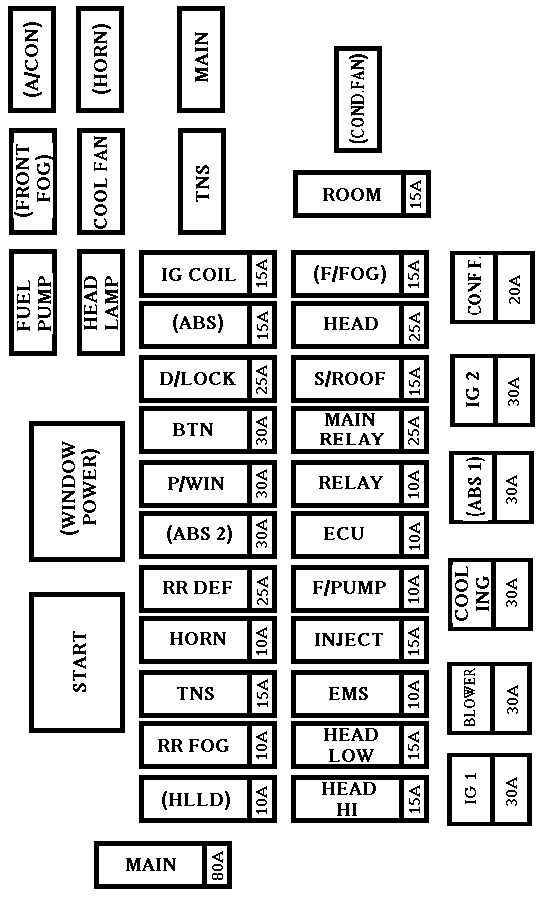
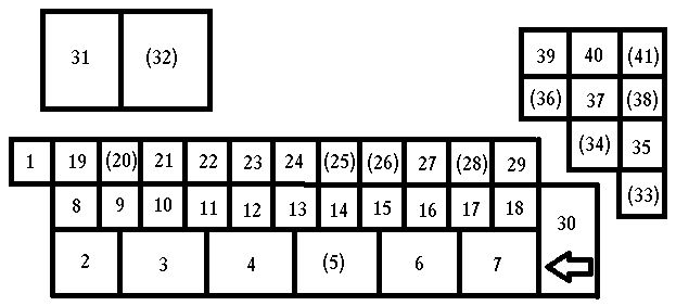
Engine compartment
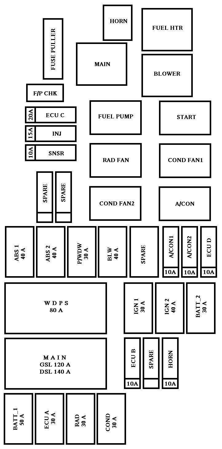
| Description | Fuse rating [A] | Protected component |
| BATT_1 | 50 | Alternator, Battery |
| ECU A | 30 | Engine control unit |
| RAD | 30 | Radiator fan |
| COND | 30 | Condenser fan |
| ECU B | 10 | Engine control unit |
| SPARE | — | Spare fuse |
| HORN | 10 | Horn |
| IGN1 | 30 | Ignition |
| IGN2 | 40 | Ignition |
| BATT_2 | Alternator, Battery | |
| MAIN | 125 | Alternator |
| MDPS | 80 | Power steering wheel |
| ABS1 | 40 | ABS |
| ABS2 | 40 | ABS |
| P/WDW | 30 | Power window |
| BLW | 40 | Blower |
| SPARE | — | Spare fuse |
| A/CON1 | 10 | Air conditioner |
| A/CON2 | 10 | Air conditioner |
| ECU D | 10 | Engine control unit |
| SNSR | 10 | Sensor |
| INJ | 15 | Injector |
| ECU C | 20 | Engine control unit |
| SPARE | — | Spare fuse |
| SPARE | — | Spare fuse |
| HORN | — | Horn relay |
| MAIN | — | Main relay |
| FUEL PUMP | — | Fuel pump relay |
| RAD FAN | — | Radiator fan relay |
| COND FAN2 | — | Condenser fan relay |
| FUEL HTR | — | Fuel filter heater relay |
| BLOWER | — | Blower motor relay |
| START | — | Start motor relay |
| COND FAN1 | — | Condenser fan relay |
| A/CON | — | Air conditioner relay |
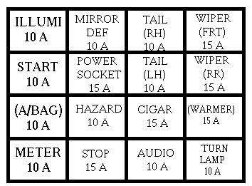
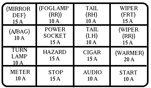
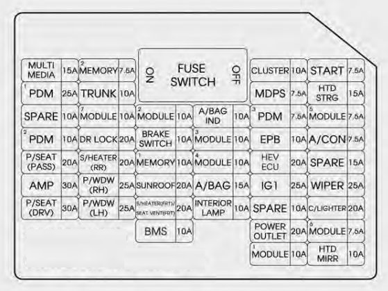
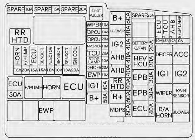
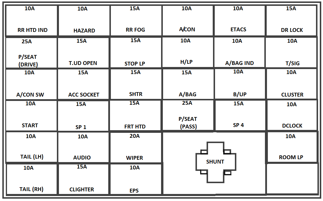
Driver-side knee bolster

| Description | Fuse rating [A] | Protected component |
| RR WIPER | 15 | Rear wiper |
| H/LP (LH) | 10 | Headlight (left) |
| FR WIPER | 25 | Front wiper |
| BLOWER | 10 | Blower |
| H/LP(RH) | 10 | Headlight (right) |
| S/ROOF | 20 | Sunroof |
| STOP LP | 15 | Stop light |
| C/DR LOCK | 20 | Central door lock |
| IGN COIL | 15 | Ignition coil |
| ABS | 10 | ABS |
| B/UP LP | 10 | Back-up light |
| SPARE | — | Spare fuse |
| C/LIGHTER | 25 | Cigar lighter |
| FOLD’G | 10 | Outside rearview mirror folding |
| HTD SEAT | 20 | Seat warmer |
| AMP | 25 | Amplifier |
| FR FOG LP | 10 | Front fog light |
| SPARE | — | Spare fuse |
| ECU | 10 | Engine control unit |
| CLUSTER | 10 | Cluster |
| P/WDW RH | 25 | Power window (right) |
| AUDIO | 10 | Audio |
| RR FOG LP | 10 | Rear fog light |
| IGN | 10 | Ignition |
| HTD GLASS | 30 | Rear window defroster |
| A/BAG | 15 | Air bag |
| TCU | 10 | Automatic transaxle control |
| SNSR | 10 | Sensor |
| SPARE | — | Spare fuse |
| MULT B/UP | 10 | Cluster, ETACS, A/C, Clock, Room lamp |
| AUDIO | 15 | Audio |
| P/WDW LH | 25 | Power window (left) |
| HTD MIRR | 10 | Outside rearview mirror heater |
| TAIL LP(LH) | 10 | Taillight (left) |
| TAIL LP(RH) | 10 | Taillight (right) |
| HAZARD | 10 | Hazard warning light |
| T/SIG LP | 10 | Turn signal light |
| A/BAG IND | 10 | Air bag warning |
| START | 10 | Start motor |
WARNING: Terminal and harness assignments for individual connectors will vary depending on vehicle equipment level, model, and market.