Mazda MPV (2002 – 2006) – fuse box diagram

Mazda MPV (2002 – 2006) – fuse box diagram

Year of production: 2002, 2003, 2004, 2005, 2006

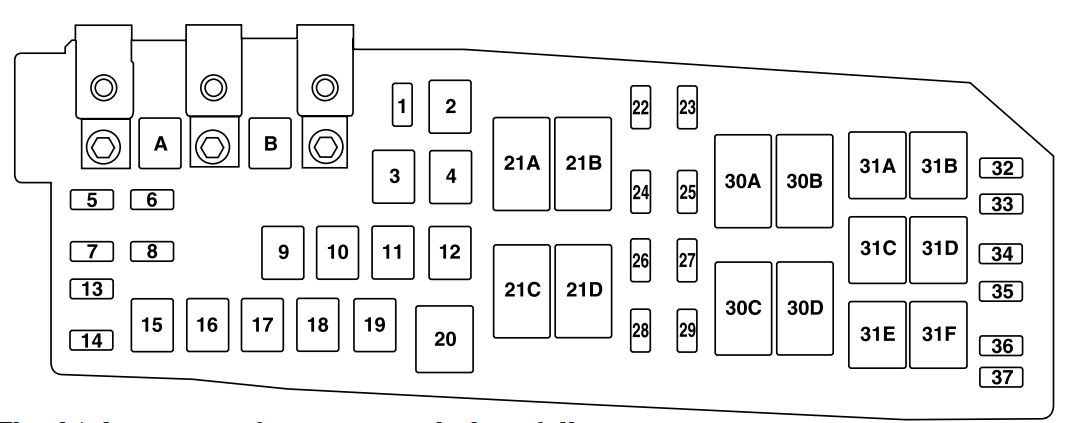
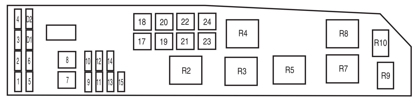
Fuse block (Engine compartment)
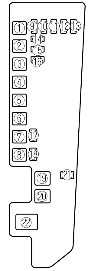
Mazda MPV - fuse box - engine compartment
Mazda MPV – fuse box –
engine compartment
Description Ampere rating [A] Description
1 DEFOG 40 Rear window defroster
2 BTN 60 STOP, HAZARD, ROOM, D.LOCK and DRL fuses
3 ABS 60 Antilock brake system, For protection of various circuits
4 FAN1 30 Cooling fan
5 FAN2 30 Cooling fan
6 HEATER 40 Heater
7 R.HEAT 30 Rear heater, For protection of various circuits
8 IG KEY2 40 A/C, P.WIND, SUN ROOF and R.WIP fuses
9 A/C 10 Air conditioner, For protection of various circuits
10 TAIL 15 Taillights
11 A/C PWR 15 Inverter
12 HORN 15 Horn
13 FOG 15 For protection of various circuits
14 EEC 5 For protection of various circuits
15 HEAD L 15 Headlight-left
16 HEAD R 15 Headlight-right
17 HID L 20
18 HID R 20
19 IG KEY1 60 METER, ENGINE and WIPER fuses
20 EGI INJ 30 For protection of various circuits
21 FUEL PUMP 20 Fuel pump
22 MAIN 120 For protection of all circuits

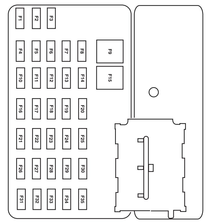
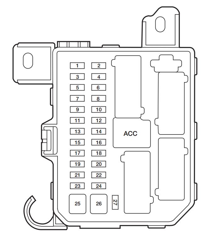
Fuse block (Driver’s side)
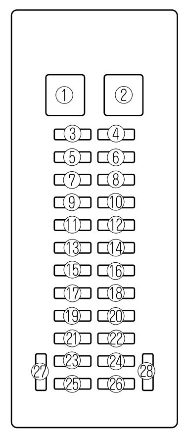
Mazda MPV - fuse box - driver's side
Mazda MPV – fuse box –
driver’s side
Description Ampere rating [A] Description
1 P.WIND 30 Power windows, For protection of various circuits
2 WIPER 20 Windshield wipers and washer
3 SUN ROOF 15 Sunroof, For protection of various circuits
4 R.WIP 10 Rear window wiper and washer
5 SEAT 20 For protection of various circuits
6 M.DEF 10 Mirror defroster, For protection of various circuits
7 A/C 10 Air conditioner, For protection of various circuits
8 DRL 10 For protection of various circuits
9
10 H/CLEAN 20 For protection of various circuits
11
12 HAZARD 10 Hazard warning flashers
13 ROOM 15 Overhead lights, Map lights, Luggage compartment light
14 AUX POWER 25 Accessory socket
15 CLOSER LH 20 For protection of various circuits
16 AUDIO 10 Audio system, For protection of various circuits
17 D.LOCK 30 Power door locks, For protection of various circuits
18 P/SEAT 30 Power seat
19 ENGINE 10 Engine control system
20 METER 10 Instrument cluster
21 STOP 15 Brake lights
22 CLOSER RH 20 For protection of various circuits
23 ACC. DELAY 30 Power windows delay, For protection of various circuits
24 METER 15 Instrument cluster, INH switch
25 ST.SIGN 10 Starter signal
26 CIGAR 25 Lighter
27
28

WARNING: Terminal and harness assignments for individual connectors will vary depending on vehicle equipment level, model, and market.

Mazda Tribute (2010 – 2011) – fuse box diagram

Mazda Tribute (2010 – 2011) – fuse box diagram

Year of production: 2010, 2011

Passenger compartment fuse panel

The fuse panel is located on the right-hand side of the center console, by the instrument panel.

Mazda Tribute - fuse box - passenger compartment
Mazda Tribute – fuse box –
passenger compartment
Fuse/relay Ampere rating [A] Description
1 30 Not used (spare)
2 15 Brake On/Off switch
3 15 Not used (spare)
4 30 Moon roof
5 10 Brake-shift interlock (BSI), Passenger compartment fuse panel
6 20 Turn signals, Stop lamps
7 10 Low beam headlamps (left)
8 10 Low beam headlamps (right)
9 15 Interior lights
10 15 Backlighting
11 10 Four wheel drive
12 7,5 Power mirror switch
13 7,5 Not used (spare)
14 10 FCIM (radio buttons), Front display module
15 10 Climate control
16 15 Not used (spare)
17 20 All lock motor feeds, Liftgate release, Liftglass release
18 20 Heated seat
19 25 Rear wiper
20 15 Datalink
21 15 Fog lamps
22 15 Park lamps
23 15 High beam headlamps
24 20 Horn relay
25 10 Demand lamps
26 10 Instrument panel cluster
27 20 Ignition switch
28 5 Radio
29 5 Instrument panel cluster
30 5 Not used (spare)
31 10 Restraints control module
32 10 Rear video camera module
33 10 Not used (spare)
34 5 Not used (spare)
35 10 Four wheel drive, Electronic power steering (EPAS)
36 5 Passive anti-theft system (PATS) transceiver
37 10 Climate control
38 20 Subwoofer/Amp (Audiophile radio)
39 20 Radio
40 20 Front power point
41 15 Driver/passenger door lock switches, Moon roof, Camera display in mirror
42 10 Not used (spare)
43 10 Rear wiper logic, Heated seats relay, Instrument cluster
44 10 Not used (spare)
45 5 Front wiper logic, Blower motor relay
46 7,5 Occupant classification system (OCS), Passenger airbag deactivation indicator (PADI)
47 30 Circuit Breaker Power windows, Moon roof
48 Delayed accessory relay

Power distribution box

The power distribution box is located in the engine compartment.

Mazda Tribute - fuse box - power distribution
Mazda Tribute – fuse box –
power distribution
Fuse/relay Ampere rating [A] Description
A 80 Midi Electronic power steering module (EPAS)
B 125 Midi Passenger compartment fuse panel
1 15* Heated mirror
2 30** Rear defroster
3 20** Rear power point (center console)
4 Not used
5 10* Powertrain control module (PCM) – keep alive power, PCM relay, Canister vent
6 15* Alternator
7 10* Liftgate latch
8 20* Trailer tow parking lamps
* 50** Anti-lock Brake System (ABS)
10 30** Front wipers
11 30** Starter
12 40** Blower motor
13 10* A/C clutch
14 15* Trailer tow turn lamps
15 Not used
16 40** Cooling fan 1
17 40** Cooling fan 2
18 20** ABS solenoid
19 30** Power seats
20 A/C clutch relay
21A Rear defroster relay
21B Fuel relay
21C Blower relay
21D PCM relay
22 20* Fuel pump
23 15* Fuel injectors
24 Not used
25 5* ABS
26 15* Ignition coils
27 10* PCM – general powertrain components malfunction indicator lamp
28 20* PCM – emission related powertrain components malfunction indicator lamp
29 15* PCM
30A Cooling fan 1 relay
30B Starter relay
30C Cooling fan main relay
30D Cooling fan 2 relay
31A Reverse lamp relay
31B Not used
31C Trailer tow left turn relay
31D Trailer tow right turn relay
31E Trailer tow park relay
31F Liftgate latch relay
32 Not used
33 PCM diode
34 Start diode
35 10* Reverse lamp relay, Speed control module, Rear defrost relay
36 Not used
* Mini fuse

** Cartridge fuse

WARNING: Terminal and harness assignments for individual connectors will vary depending on vehicle equipment level, model, and market.

Mazda Tribute (2009) – fuse box diagram

Mazda Tribute (2009) – fuse box diagram

Year of production: 2009

Passenger compartment fuse panel

The fuse panel is located on the right-hand side of the center console, by the instrument panel.

Mazda Tribute - fuse box - passenger compartment
Mazda Tribute – fuse box –
passenger compartment
Fuse/relay Ampere rating [A] Description
1 30 Not used (spare)
2 15 Brake On/Off switch
3 15 Not used (spare)
4 30 Moon roof
5 10 Brake Shift Interlock (BSI), SPDJB
6 20 Turn signals, Stop lamps
7 10 Low beam headlamps (left)
8 10 Low beam headlamps (right)
9 15 Interior lights
10 15 Backlighting
11 10 Four wheel drive
12 7,5 Power mirror switch
13 7,5 Not used (spare)
14 10 FCIM (radio buttons), Front display module
15 10 Climate control
16 15 Not used (spare)
17 20 All lock motor feeds, Liftgate release, Liftglass release
18 20 Heated seat
19 25 Rear wiper
20 15 Datalink
21 15 Fog lamps
22 15 Park lamps
23 15 High beam headlamps
24 20 Horn relay
25 10 Demand lamps
26 10 Instrument panel cluster
27 20 Ignition switch
28 5 Radio
29 5 Instrument panel cluster
30 5 Not used (spare)
31 10 Restraints control module
32 10 Not used (spare)
33 10 Not used (spare)
34 5 Speed control deactivate switch, ABS
35 10 Four wheel drive, Electronic power steering (EPAS)
36 5 PATS transceiver
37 10 Climate control
38 20 Subwoofer/Amp (Audiophile radio)
39 20 Radio
40 20 Front power point
41 15 Driver/passenger door lock switches
42 10 Not used (spare)
43 10 Rear wiper logic, Heated seats relay, Instrument cluster
44 10 Not used (spare)
45 5 Front wiper logic, Blower motor relay
46 7,5 OCS (restraints), PADI (restraints)
47 30 Circuit Breaker Power windows, Moon roof
48 Delayed accessory relay

Power distribution box

The power distribution box is located in the engine compartment.

Mazda Tribute - fuse box - power distribution
Mazda Tribute – fuse box –
power distribution
Fuse/relay Ampere rating [A] Description
A 80 Midi Electronic power steering module (EPAS)
B 125 Midi SPDJB
1 15* Heated mirror
2 30** Rear defroster
3 20** Rear power point (center console)
4 Not used
5 10* Powertrain Control Module (PCM) Keep Alive power, PCM relay, Canister vent
6 15* Alternator
7 10* Liftgate latch
8 20* Trailer tow parking lamps
* 50** Anti-lock Brake System (ABS)
10 30** Front wipers
11 30** Starter
12 40** Blower motor
13 10* A/C clutch
14 15* Trailer tow turn lamps
15 Not used
16 40** Cooling fan 1
17 40** Cooling fan 2
18 20** ABS solenoid
19 30** Power seats
20 A/C clutch relay
21A Rear defroster relay
21B Fuel relay
21C Blower relay
21D PCM relay
22 20* Fuel pump
23 15* Fuel injectors
24 10* Not used
25 Not used
26 15* Ignition coils
27 10* PCM non mil-malfunction indicator lamp
28 20* PCM mil-on malfunction indicator lamp
29 15* Powertrain Control Module
30A Cooling fan 1 relay
30B Starter relay
30C Cooling fan main relay
30D Cooling fan 2 relay
31A Reverse lamp relay
31B Not used
31C Trailer tow left turn relay
31D Trailer tow right turn relay
31E Trailer tow park relay
31F Liftgate latch relay
32 Not used
33 PCM diode
34 Start diode
35 10* Reverse lamp relay, Speed control module, Rear defrost relay
36 Not used
37 Not used
* Mini fuse

** Cartridge fuse

WARNING: Terminal and harness assignments for individual connectors will vary depending on vehicle equipment level, model, and market.

Mazda Tribute (2008) – fuse box diagram

Mazda Tribute (2008) – fuse box diagram

Year of production: 2008

Passenger compartment fuse panel

The fuse panel is located on the right-hand side of the center console, by the instrument panel.

Mazda Tribute - fuse box - passenger compartment
Mazda Tribute – fuse box –
passenger compartment
Fuse/relay Ampere rating [A] Description
1 30 Not used (spare)
2 15 Brake On/Off switch
3 15 Not used (spare)
4 30 Not used (spare)
5 10 Brake Shift Interlock (BSI), SPDJB
6 20 Turn signals, Stop lamps
7 10 Low beam headlamps (left)
8 10 Low beam headlamps (right)
9 15 Interior lights
10 15 Backlighting
11 10 Four wheel drive
12 7,5 Power mirror switch
13 7,5 Canister vent
14 10 FCIM (radio buttons), Front display module
15 10 Climate control
16 15 Not used (spare)
17 20 All lock motor feeds, Liftgate release, Liftglass release
18 20 Heated seat
19 25 Rear wiper
20 15 Datalink
21 15 Fog lamps
22 15 Park lamps
23 15 High beam headlamps
24 20 Horn relay
25 10 Demand lamps
26 10 Instrument panel cluster
27 20 Ignition switch
28 5 Radio
29 5 Instrument panel cluster
30 5 Overdrive cancel
31 10 Not used (spare)
32 10 Restraints control module
33 10 Speed control switch
34 5 Speed control deactivate switch, ABS
35 10 Four wheel drive, EPAS (steering)
36 5 PATS transceiver
37 10 Climate control
38 20 Subwoofer/Amp (Audiophile radio)
39 20 Radio
40 20 Front power point
41 15 Driver/passenger door lock switches
42 10 Not used (spare)
43 10 Rear wiper logic, Heated seats relay
44 10 Not used (spare)
45 5 Front wiper logic, Blower motor relay
46 7,5 OCS (restraints), PADI (restraints)
47 30 Circuit Breaker Power windows, Moon roof
48 Delayed accessory relay

Power distribution box

The power distribution box is located in the engine compartment.

Mazda Tribute - fuse box - power distribution
Mazda Tribute – fuse box –
power distribution
Fuse/relay Ampere rating [A] Description
A 80 Midi EPAS
B 125 Midi SPDJB
1 15* Heated mirror
2 30** Rear defroster
3 20** Rear power point (center console)
4 20** Fuel pump
5 10* Powertrain Control Module (PCM) Keep Alive power
6 15* Alternator
7 10* Reverse lamps
8 20* Trailer tow parking lamps
* 50** Anti-lock Brake System (ABS)
10 30** Front wipers
11 30** Starter
12 40** Blower motor
13 10* A/C clutch
14 15* Trailer tow turn lamps
15 Not used
16 40** Cooling fan 1
17 40** Cooling fan 2
18 20** ABS solenoid
19 30** Power seats
20 A/C clutch relay
21A Rear defroster relay
21B Not used
21C Blower relay
21D PCM relay
22 Not used
23 Not used
24 10* PCM transmission
25 Not used
26 10* PCM mil
27 10* PCM non-mil
28 15* PCM
29 15* Ignition coils
30A Cooling fan 1 relay
30B Starter relay
30C Cooling fan main relay
30D Cooling fan 2 relay
31A Reverse lamp relay
31B Fuel pump relay
31C Trailer tow left turn relay
31D Trailer tow right turn relay
31E Trailer tow park relay
31F Not used
32 A/C clutch diode
33 PCM diode
34 Start diode
35 10* Reverse lamp relay, Speed control module, Rear defrost relay
36 Not used
37 Not used
* Mini fuse

** Cartridge fuse

WARNING: Terminal and harness assignments for individual connectors will vary depending on vehicle equipment level, model, and market.

Mazda Tribute (2006) – fuse box diagram

Mazda Tribute (2006) – fuse box diagram

Year of production: 2006

Passenger compartment fuse panel

The fuse panel is located on the right-hand side of the center console, by the instrument panel.

Mazda Tribute - fuse box - passenger compartment
Mazda Tribute – fuse box –
passenger compartment
Fuse/relay Ampere rating [A] Description
1 15* Trailer tow park lamps
2 5* Radio (illumination)
3 15* Front and rear park lamps
4 10* Ignition switch
5 2* Powertrain Control Module (PCM relay), Fuel pump relay, Main fan relay, High/Low speed fan relay 2, PATS module
6 15* Center High-Mounted Stop Lamp (CHMSL), Stop lamps, PCM, Anti-lock Brake System (ABS), Speed control, Brake On-Off switch
7 10* Instrument cluster, Diagnostic connector, Power mirror switch, Radio
8 Not used
9 30** Power door locks, Power seats
10 15* Heated mirrors
11 15* Sunroof
12 Not used
13 Not used
14 Not used
15 30** Power windows
16 15* Subwoofer
17 15* Low beams
18 10* 4WD
19 Not used
20 15* Horn
21 10* Rear wiper motor, Rear wiper washer
22 10* Electrochromatic mirror, Instrument cluster
23 5* Radio (power)
24 20* Cigar lighter
25 20 Front wiper motor, Front wiper washer
26 5* Climate control system mode switch
27 5* Canister vent, Speed control cancel switch
28 10* Instrument cluster
29 Not used
30 Not used
31 Not used
32 10* Brake-Transmission shift lock
33 15* Air bag module, Passenger Air bag Deactivation (PAD) indicator lamp, Occupant Classification Sensor (OCS)
34 5* ABS module, Evac and Fill, Speed control
35 5* Heated seats module, 4WD
* Mini fuse

** Cartridge fuse

Power distribution box

The power distribution box is located in the engine compartment.

Mazda Tribute - fuse box - power distribution
Mazda Tribute – fuse box –
power distribution
Fuse/relay Ampere rating [A] Description
1 Not used
2 25* Headlamp power
3 25* High beams, Turn signals, Interior lamps, Headlamp power
4 5* Keep Alive Power (KA PWR)
5 15* Heated Exhaust Gas Oxygen (HEGO) sensors
6 20* Fuel pump
7 40** RUN/ACC relay – Cigar lighter, Front and rear wipers
8 30** Powertrain Control Module (PCM), Injectors and coil
9 15* Alternator
10 30* Heated seats
11 10* PCM
12 20* Power point
13 20* Fog lamps
14 15* A/C clutch, A/C relay
15 30* Anti-lock Brake System (ABS) solenoid
16 25* I/P fuse panel (RUN/START)
17 50** Ignition (main)
18 40** Blower motor
19 40** Accessory delay relay – Subwoofer and 4WD, Low beam
20 60** ABS
21 40** Horn, CHMSL, Cluster, Power locks and power seats
22 40** (I4) Cooling fan
50** (V6)
23 40** Rear defroster, Park lamps relay
24 40** (I4) High/Low speed fan
50** (V6)
25 Shunt
R2 PCM relay
R3 Fuel pump relay
R4 Cooling fan relay
R5 High/Low speed fan relay 1
R6 Blower motor relay
R7 Starter relay
R8 High/Low speed fan relay 2
R9 Fog lamps relay
R10 A/C relay
D1 Not used
D2 A/C diode
* Mini fuse

** Cartridge fuse

WARNING: Terminal and harness assignments for individual connectors will vary depending on vehicle equipment level, model, and market.

Mazda Tribute (2005) – fuse box diagram

Mazda Tribute (2005) – fuse box diagram

Year of production: 2005

Passenger compartment fuse panel

The fuse panel is located on the right-hand side of the center console, by the instrument panel.

Mazda Tribute - fuse box - passenger compartment
Mazda Tribute – fuse box –
passenger compartment
Fuse/relay Ampere rating [A] Description
1 15* Trailer tow park lamps
2 5* Radio (illumination)
3 15* Front and rear park lamps
4 10* Ignition switch
5 2* Powertrain Control Module (PCM relay), Fuel pump relay, Main fan relay, High/Low speed fan relay 2, PATS module
6 15* Center High-Mounted Stop Lamp (CHMSL), Stop lamps, PCM, Anti-lock Brake System (ABS), Speed control, Brake On-Off switch
7 10* Instrument cluster, Diagnostic connector, Power mirror switch, Radio
8 Not used
9 30** Power door locks, Power seats
10 15* Heated mirrors
11 15* Sunroof
12 Not used
13 Not used
14 Not used
15 30** Power windows
16 15* Subwoofer
17 15* Low beams
18 10* 4WD
19 Not used
20 15* Horn
21 10* Rear wiper motor, Rear wiper washer
22 10* Electrochromatic mirror, Instrument cluster
23 5* Radio (power)
24 20* Cigar lighter
25 20 Front wiper motor, Front wiper washer
26 5* Climate control system mode switch
27 5* Canister vent, Speed control cancel switch
28 10* Instrument cluster
29 Not used
30 Not used
31 Not used
32 10* Brake-Transmission shift lock
33 15* Air bag module, Passenger Air bag Deactivation (PAD) indicator lamp, Occupant Classification Sensor (OCS)
34 5* ABS module, Evac and Fill, Speed control
35 5* Heated seats module, 4WD
* Mini fuse

** Cartridge fuse

Power distribution box

The power distribution box is located in the engine compartment.

Mazda Tribute - fuse box - power distribution
Mazda Tribute – fuse box –
power distribution
Fuse/relay Ampere rating [A] Description
1 25* I/P fuse panel (RUN/START)
2 25* Headlamp power
3 25* High beams, Turn signals, Interior lamps, Headlamp power
4 5* Keep Alive Power (KA PWR)
5 15* Heated Exhaust Gas Oxygen (HEGO) sensors
6 20* Fuel pump
7 40** RUN/ACC relay – Cigar lighter, Front and rear wipers
8 30** Powertrain Control Module (PCM), Injectors and coil
9 15* Alternator
10 30* Heated seats
11 10* PCM
12 20* Power point
13 20* Fog lamps
14 15* A/C clutch, A/C relay
15 30* Anti-lock Brake System (ABS) solenoid
17 50** Ignition (main)
18 40** Blower motor
19 40** Accessory delay relay – Subwoofer and 4WD, Low beam
20 60** ABS
21 40** Horn, CHMSL, Cluster, Power locks and power seats
22 40** (I4) Cooling fan
50** (V6)
23 40** Rear defroster, Park lamps relay
24 40** (I4) High/Low speed fan
50** (V6)
25 Shunt
R2 PCM relay
R3 Fuel pump relay
R4 Cooling fan relay
R5 High/Low speed fan relay 1
R7 Starter relay
R8 High/Low speed fan relay 2
R9 Fog lamps relay
R10 A/C relay
D1 Starter diode
D2 A/C diode
* Mini fuse

** Cartridge fuse

WARNING: Terminal and harness assignments for individual connectors will vary depending on vehicle equipment level, model, and market.

Mazda Tribute (2003 – 2004) – fuse box diagram

Mazda Tribute (2003 – 2004) – fuse box diagram

Year of production: 2003, 2004

Passenger compartment fuse panel

The fuse panel is located below and to the left of the steering wheel by the brake pedal.

Mazda Tribute - fuse box - passenger compartment
Mazda Tribute – fuse box –
passenger compartment
Fuse/relay Ampere rating [A] Description
1 5 Canister Vent Control Solenoid
2 5 Blower relay (coil), Pressure switch to PCM
3 10 Rear Wiper Motor, Rear Washer Motor, Rear Wiper Relay (coil)
4 10 Four Wheel Drive Control Module, Cluster (Restraints Control Warning)
5 5 ABS unit (EVAC & FILL), ASC unit, Restraints Control Module (RCM), ASC main SW to ASC unit, Clock spring switch
6 10 Flasher unit, Reversing lamps, Park Aid Module (PAM)
7 10 Passive Anti-theft Transceiver (PATS), RCM, EEC fuse
8 10 Cluster, Shift lock relay (coil), O/D signal to PCM, GEM, E/C autolamp mirror
9 3 PCM relay (coil), Fan relay 1, 2, 3 (coil), A/C relay (coil)
10 20 Front wiper motor, Front washer motor
11 10 ACC relay (coil), Key interlock solenoid, GEM
12 5 Radio
13 Not used
14 20 Cigar lighter
15 15 Park lamp relay, Front position lamps, License lamps, Tail lamps, Park lamp relay (coil), Trailer fuse, Illumination fuse
16 10 Cluster, Power mirror, GEM, Heated seats
17 15 Sun roof motor
18 5 Illumination for: Cluster, Heater unit, Radio, Hazard switch, Rear defrost switch, 4WD switch, Front fog switch
19 10 Subwoofer amp
20 15 Turn Indicators, Front Side Turn Lamps, Front turn lamps, Rear turn lamps, Trailer turn, Flasher unit
21 10 Trailer position lamps
22 15 Not used
23 15 Horn relay
24 15 Stoplamps, High mounted stoplamp, Trailer stoplamp, ABS unit, ASC unit (Brake Pedal Position Switch), PCM, Shift solenoid
25 30 Power window motors
26 30 Power door lock motors, GEM (door lock relay coil), Power seat, 4WD relay
27 10 GEM, Audio, Cluster, Interior lamp, Map lamp, Cargo lamp, Datalink connector
ACC Accessory relay

Power distribution box

The power distribution box is located in the engine compartment.

Mazda Tribute - fuse box - power distribution
Mazda Tribute – fuse box –
power distribution
Fuse/relay Ampere rating [A] Description
Horn 15 Horn
H/L LH 15* Headlamp (high/low left, High beams)
H/L RH 15* Headlamp (high/low right, High beams)
EEC 5* EEC (KPWR)
HEGO 15* HEGO 1,2, CMS 1,2, VMV
FUEL 20* Fuel pump, EEC (FPM)
DIODE
DIODE
H/L RELAY MICRO Headlamp (high/low, right/left relay)
HTD SEATS 30 Heated seats (if equipped)
INJ 30** EEC (VPWR), EVR, MAF, IAC, Bulkhead, HEGO fuse
MAIN 120 Main
ALT 15* Alternator/ Regulator
(DRL) 15* Daytime Running Lamps (DRL) unit (feed), DRL relay
(DRLZ) (HELV) 15*(DRLZ) 10(HLEV) DRL module, HLEV
PWR 1 15* Auxiliary power point
FOG 20* Foglamps, Foglamp indicator
A/C 15* A/C clutch
(ABS) 25* Anti-Lock Brake System (ABS) SOL, EVAC & FILL
PWR 2 15* Auxiliary power point
IG MAIN 40** Starter
HTR 40** Blower motor, Blower motor relay
BTN 1 40** JB – Accessory relay, Radio, TNS relay, Cigar lighter, Cluster, Power mirror, GEM, Accessory delay relay, Power windows, Power moonroof
(ABS) 60** ABS motor, EVAC & FILL
BTN 2 40** JB – Radio, CD changer, Cluster, Dome lamps, Map lamps, Cargo lamps, Horn relay, GEM, Power locks, Speed control
MAIN FAN 40** (2.0L) 50(3.0L) Main fan
R DEF 30** Rear defroster
ADD FAN 40**(2.0L) 50(3.0L) Add fan
EEC MAIN ISO EEC relay
FUEL PUMP ISO Fuel pump relay
MAIN FAN ISO Low-speed fan control relay (2.0L engine) High-speed fan control relay 1 (3.0L engine)
ADD FAN ISO High-speed fan control relay 1 (2.0L engine) Low-speed fan control relay (3.0L engine)
DEF RELAY ISO Rear defroster relay
ST RELAY ISO Starter Relay
ADD FAN 2 ISO High Speed Fan Control Relay 2 (3.0L Engine)

Medium Speed Fan Control Relay (2.0L Engine)

FOG RELAY MICRO Foglamp Relay
A/C RELAY MICRO A/C Clutch Relay

WARNING: Terminal and harness assignments for individual connectors will vary depending on vehicle equipment level, model, and market.

Hyundai Elantra (2014 – 2016) – fuse box diagram

Hyundai Elantra (2014 – 2016) – fuse box diagram

Year of production: 2014, 2015, 2016

Instrument panel (Driver’s side fuse panel)

Hyundai Elantra - fuse box - instrument panel
Hyundai Elantra – fuse box – instrument panel
Description Fuse rating Protected component
START 7,5 W/O Smart Key : ICM Relay Box(Burglar Alarm Relay), With Smart Key : A/T – Transaxle Range Switch, M/T – ECM, E/R Fuse & Relay Box(Start 1 Relay), Smart Key Control Module
A/BAG 15 SRS Control Module, Passenger Weight Classification Sensor
A/BAG IND 7,5 Instrument Cluster
CLUSTER 7,5 ISG LDC (Audio), Cluster (ISG)
C/LIGHTER 15 Cigarette Lighter
BCM 7,5 Smart Key Control Module, BCM
A/CON SWITCH 7,5 A/C Control Module
MODULE 2 7,5 Electro Chromic Mirror, ESC Off Switch
MDPS 10 EPS Control Module
MODULE 4 7,5 Rear Parking Assist Sensor LH/RH (IN/OUT), A/C Control Module(Auto A/C), ATM Lever Indicator
IG1 20 E/R Fuse & Relay Box(Fuse – TCU 1, B/UP LP, ECU 3, ABS 3)
PDM 3 7,5 Smart Key Control Module
POWER OUTLET FRT 20 Power Outlet
MODULE 6 10 AMP, Power Outside Mirror Switch, Audio, A/V & Navigation Head Unit, Digital Clock
HTD MIRR 10 Driver/Passenger Power Outside Mirror, A/C Control Module
MODULE 3 7,5 Audio, Tire Pressure Monitoring Module, Digital Clock, BCM, Instrument Cluster, Driver/Passenger Seat Warmer Module
BRAKE SWITCH 10
SPARE 15
SUNROOF 15 Sunroof
SPARE 15
SPARE 15
BLOWER 10 Manual A/C – A/C Control Module, ECM/PCM, Blower Resistor
INTERIOR LAMP 10 Luggage Lamp, Vanity Lamp LH/RH, Room Lamp, Overhead Console Lamp, Ignition Key Ill. & Door Warning Switch(W/O Smart Key)
TRUNK 10 Trunk Relay
MODULE 1 7,5 Sport Mode Switch(A/T), Key Solenoid(W/O Smart Key)
SPARE 15
S/HEATER RR 15 Rear Seat Warmer Switch LH/RH
MODULE 7 7,5 Smart Key Control Module, BCM
MULTIMEDIA 15 Audio, A/V & Navigation Head Unit
P/WDW RH 25 P/WDW RH Relay
PDM 2 7,5 Smart Key Control Module, Start Stop Button Switch
SPARE 10
WIPER FRT 25 ICM Relay Box(Rain Sensor Relay), Multifunction Switch, Wiper Motor, E/R Fuse & Relay Box(Wiper Relay)
MODULE 5 7,5 Cluster Ionizer(Auto A/C), Rain Sensor, Sunroof
SPARE 7,5
AMP 25 AMP
PDM 1 25 Smart Key Control Module
SPARE 20
A/CON 7,5 A/C Control Module, E/R Fuse & Relay Box(Blower Relay)
MEMORY 10 Tire Pressure Monitoring Module, BCM, Auto Light & Photo Sensor, Instrument Cluster, Data Link Connector, Smart Junction Box Upgrade Connector, Electro Chromic Mirror, A/C Control Module, Digital Clock
P/WDW LH 25 P/WDW LH Relay, Driver Safety Power Window Module
DR LOCK 20 Door Lock Relay, Door Unlock Relay, ICM Relay Box(Two Turn Relay)
P/SEAT DRV 30 Driver Seat Manual Switch

Engine compartment fuse panel

Hyundai Elantra - fuse box - engine compartment
Hyundai Elantra – fuse box – engine compartment
Description Fuse rating Protected component
MULTI FUSE MDPS 80 EPS Control Module
B+1 60 Smart Junction Box(ARISU 1 (4CH), IPS 1, FUSE – P/WDW LH, P/WDW RH, TRUNK, AMP 1)
C/FAN 40 C/FAN Lo Relay, C/FAN Hi Relay
ABS 1 40 ESC Module, Multipurpose Check Connector
RR HTD 40 RR HTD Relay
BLOWER 40 Blower Relay
SPARE 40
B+2 60 Smart Junction Box(Turn Signal Lamp Sound Relay, ARISU 2 (4CH), IPS (1CH), IPS (2CH), FUSE – P/SEAT DRV, SUNROOF)
FUSE B/UP LP 10 Electro Chromic Mirror, A/V & Navigation Head Unit, Rear Combination Lamp (In) LH/RH, M/T – Back-Up Lamp Switch, BCM, Instrument Cluster
TCU 1 15 M/T – Vehicle Speed Sensor, A/T – Transaxle Range Switch
ABS 3 10 ESC Module, Multipurpose Check Connector
ECU 3 10 Stop Lamp Switch, M/T – ECM, A/T – PCM
WIPER 10 Rain Sensor, M/T – ECM, A/T – PCM
B+3 50 Smart Junction Box (Leak Current Autocut Device, FUSE – MODULE 1, PDM 1, PDM 2, DR LOCK)
EMS 40 EMS Box(Engine Control Relay, FUSE – ECU 4, A/CON, F/PUMP)
ISG INVERTER 50 Oil Pump Inverter
STOP LP 15 Stop Lamp Switch, Smart Key Control Module
S/HEATER FRT 20 Driver/Passenger Seat Warmer Module
HORN 15 Horn Relay
IG 2 40 W/O Smart Key : Ignition Switch, Start 1 Relay, With Smart Key : PDM 4 (IG2) Relay, Start 1 Relay
ABS 2 30 ESC Module, Multipurpose Check Connector
IG 1 40 W/O Smart Key : Ignition Switch, With Smart Key : PDM 3 (IG1) Relay, PDM 2 (ACC) Relay
F/PUMP 15 F/PUMP Relay
ECU 4 15 PCM (A/T), ECM (M/T)
A/CON 10 A/C COMP Relay
INJECTOR 10 Injector #1 / #2 / #3 / #4, A/C COMP Relay, F/PUMP Relay
ECU 2 10 PCM (A/T), ECM (M/T)
IGN COIL 1 20 Ignition Coil #1 / #2 / #3 / #4, Condenser
ECU 1 20
SENSOR 2 10 Immobilizer Module, Camshaft Position Sensor #1 / #2
SENSOR 1 10 Oxygen Sensor (UP/DOWN), Canister Close Valve, Variable Intake Solenoid Valve, Oil Control Valve #1 / #2, Purge Control Solenoid Valve, C/FAN LO Relay, C/FAN HI Relay
SPARE 10
SPARE 15
SPARE 20

WARNING: Terminal and harness assignments for individual connectors will vary depending on vehicle equipment level, model, and market.

Hyundai Elantra (2011 – 2013) – fuse box diagram

Hyundai Elantra (2011 – 2013) – fuse box diagram

Year of production: 2011, 2012, 2013

Instrument panel (Driver’s side fuse panel)

Description Fuse rating Protected component
START 7,5 W/O Smart Key : ICM Relay Box(Burglar Alarm Relay), With Smart Key : A/T – Transaxle Range Switch, M/T – ECM, E/R Fuse & Relay Box(Start 1 Relay), Smart Key Control Module
A/BAG 15 SRS Control Module, Passenger Weight Classification Sensor
A/BAG IND 7,5 Instrument Cluster
MDPS 7,5 EPS Control Module
POWER OUTLET FRT 15 Power Outlet
BCM 7,5 Smart Key Control Module, BCM
A/CON SW 7,5 A/C Control Module
MODULE 2 7,5 Electro Chromic Mirror, ESC Off Switch
SPARE 1 10
MODULE 4 7,5 Rear Parking Assist Sensor LH/RH (IN/OUT), A/C Control Module(Auto A/C), ATM Lever Indicator
IG1 20 E/R Fuse & Relay Box(Fuse – TCU 1, B/UP LP, ECU 3, ABS 3)
PDM 3 7,5 Smart Key Control Module
C/LIGHTER 20 Cigarette Lighter
MODULE 6 10 AMP, Power Outside Mirror Switch, Audio, A/V & Navigation Head Unit, Digital Clock
HTD MIRR 10 Driver/Passenger Power Outside Mirror, A/C Control Module
MODULE 3 7,5 Audio, Tire Pressure Monitoring Module, Digital Clock, BCM, Instrument Cluster, Driver/Passenger Seat Warmer Module
SPARE 3 10
SUNROOF 15 Sunroof
S/HEATER RR RH 15 Rear Seat Warmer Switch RH
SPARE 2 15
BLOWER 10 Manual A/C – A/C Control Module, ECM/PCM, Blower Resistor
I.O.D 1 10 Luggage Lamp, Vanity Lamp LH/RH, Room Lamp, Overhead Console Lamp, Ignition Key Ill. & Door Warning Switch(W/O Smart Key)
TRUNK 10 Trunk Relay
MODULE 1 7,5 Sport Mode Switch(A/T), Key Solenoid(W/O Smart Key)
SPARE 4 15
S/HEATER RR LH 15 Rear Seat Warmer Switch LH
MODULE 7 7,5 Smart Key Control Module, BCM
I.O.D 2 20 Audio, A/V & Navigation Head Unit
P/WDW RH 25 P/WDW RH Relay
PDM 2 7,5 Smart Key Control Module, Start Stop Button Switch
SPARE 6 10
WIPER FRT 25 ICM Relay Box(Rain Sensor Relay), Multifunction Switch, Wiper Motor, E/R Fuse & Relay Box(Wiper Relay)
MODULE 5 7,5 Cluster Ionizer(Auto A/C), Rain Sensor, Sunroof
AMP 1 25 AMP
PDM 1 25 Smart Key Control Module
SPARE 5 20
A/CON 7,5 A/C Control Module, E/R Fuse & Relay Box(Blower Relay)
I.O.D 4 10 Tire Pressure Monitoring Module, BCM, Auto Light & Photo Sensor, Instrument Cluster, Data Link Connector, Smart Junction Box Upgrade Connector, Electro Chromic Mirror, A/C Control Module, Digital Clock
P/WDW LH 25 P/WDW LH Relay, Driver Safety Power Window Module
DR LOCK 20 Door Lock Relay, Door Unlock Relay, ICM Relay Box(Two Turn Relay)
P/SEAT DRV 30 Driver Seat Manual Switch

Engine compartment main fuse panel

Description Fuse rating Protected component
MULTI FUSE MDPS 80 EPS Control Module
B+1 60 Smart Junction Box(ARISU 1 (4CH), IPS 1, FUSE – P/WDW LH, P/WDW RH, TRUNK, AMP 1)
C/FAN 40 C/FAN Lo Relay, C/FAN Hi Relay
ABS 1 40 ESC Module, Multipurpose Check Connector
RR HTD 40 RR HTD Relay
BLOWER 40 Blower Relay
SPARE 40
B+2 60 Smart Junction Box(Turn Signal Lamp Sound Relay, ARISU 2 (4CH), IPS (1CH), IPS (2CH), FUSE – P/SEAT DRV, SUNROOF)
FUSE B/UP LP 10 Electro Chromic Mirror, A/V & Navigation Head Unit, Rear Combination Lamp (In) LH/RH, M/T – Back-Up Lamp Switch, BCM, Instrument Cluster
TCU 1 15 M/T – Vehicle Speed Sensor, A/T – Transaxle Range Switch
ABS 3 10 ESC Module, Multipurpose Check Connector
ECU 3 10 Stop Lamp Switch, M/T – ECM, A/T – PCM
WIPER 10 Rain Sensor, M/T – ECM, A/T – PCM
B+3 50 Smart Junction Box (Leak Current Autocut Device, FUSE – MODULE 1, PDM 1, PDM 2, DR LOCK)
EMS 40 EMS Box(Engine Control Relay, FUSE – ECU 4, A/CON, F/PUMP)
STOP LP 15 Stop Lamp Switch, Smart Key Control Module
S/HEATER FRT 20 Driver/Passenger Seat Warmer Module
HORN 15 Horn Relay
IG 2 40 W/O Smart Key : Ignition Switch, Start 1 Relay, With Smart Key : PDM 4 (IG2) Relay, Start 1 Relay
ABS 2 30 ESC Module, Multipurpose Check Connector
IG 1 40 W/O Smart Key : Ignition Switch, With Smart Key : PDM 3 (IG1) Relay, PDM 2 (ACC) Relay
F/PUMP 15 F/PUMP Relay
ECU 4 15 PCM (A/T), ECM (M/T)
A/CON 10 A/C COMP Relay
INJECTOR 10 Injector #1 / #2 / #3 / #4, A/C COMP Relay, F/PUMP Relay
ECU 2 10 PCM (A/T), ECM (M/T)
IGN COIL 1 20 Ignition Coil #1 / #2 / #3 / #4, Condenser
ECU 1 20
SENSOR 2 10 Immobilizer Module, Camshaft Position Sensor #1 / #2
SENSOR 1 10 Oxygen Sensor (UP/DOWN), Canister Close Valve, Variable Intake Solenoid Valve, Oil Control Valve #1 / #2, Purge Control Solenoid Valve, C/FAN LO Relay, C/FAN HI Relay
SPARE 10
SPARE 15
SPARE 20

WARNING: Terminal and harness assignments for individual connectors will vary depending on vehicle equipment level, model, and market.

Hyundai Elantra (2010) – fuse box diagram

Hyundai Elantra (2010) – fuse box diagram

Year of production: 2010

Driver’s side fuse panel

Description Fuse rating Protected component
START 10 Ignition lock switch, Antitheft alarm, Transaxle range switch
A/CON SW 10 A/C control module
HTD MIRR 10 Outside heated mirror motor
SEAT HTR 15 Seat warmer switch
A/CON 10 Blower relay, A/C control module, Sunroof control module
HEAD LAMP 10 Head lamp relay
FR WIPER 25 Front wiper relay
RR WIPER 15 (Spare)
DRL 10 Daytime running lamp unit
WCS 10 Occupant classification sensor
P/WDW DR 25 Power window main switch, Rear power window switch(LH)
CLOCK 10 Digital clock, Audio
C/LIGHTER 15 Power outlet
DR LOCK 20 Sunroof control module, Door unlock/lock relay
DEICER 15
STOP 15 Stop lamp switch
ROOM LP 15 Trunk room lamp, Dome lamp, Map lamp, Digital clock, Home link
AUDIO 15 Audio
T/LID 15 Trunk lid relay
AMP 25 Amplifier
SAFETY P/WDW 25 Safety power window module
P/WDW ASS 25 Front & rear power window switch(RH), Power window main switch
P/OUTLET 15 Power outlet
T/SIG 10 Hazard switch
A/BAG IND 10 Airbag indicator(instrument cluster)
CLUSTER 10 Instrument cluster
A/BAG 15 SRS control module
IGN 1 15 EPS module, ESC switch
SPARE 15 (Spare)
TAIL RH 10 Head lamp(RH), Glove box lamp, Rear combination lamp(RH), License lamp
TAIL LH 10 Head lamp(LH), Power window main switch, Rear combination lamp(LH), License lamp

Engine compartment

Description Fuse rating Protected component
FUSIBLE LINK ALTERNATOR 125 Generator
EPS 80 EPS control module
ABS.2 20 ESC control module, ABS control module, Multi purpose check connector
ABS.1 40 ESC control module, ABS control module, Multi purpose check connector
B+.1 50 Instrument panel junction box
RR HTD 40 Instrument panel junction box
BLOWER 40 Blower relay
C/FAN 40 Condenser fan #1, 2 relay
B+.2 50 Instrument panel junction box
IGN.2 40 Ignition switch, Start relay
IGN.1 30 Ignition switch
ECU 30 Main relay, ECM
FUSE SPARE.1 20 (Spare)
FR FOG 15 Front fog lamp relay
A/CON 10 A/C relay
HAZARD 15 Hazard switch, Hazard relay
F/PUMP 15 Fuel pump relay
INJ 15 A/C relay, Fuel pump relay, Injector #1,2,3,4, ECM, Idle speed actuator etc.
SNSR.2 10 Pulse generator ‘A’, ‘B’, Stop lamp switch, Vehicle speed sensor etc.
HORN 15 Horn relay
ABS 10 ESC control module, ABS control module, Multi purpose check connector
ECU.2 10 ECM
B/UP 10 Back up lamp switch, Transaxle range switch, Cruise control module
H/LP LO RH 10 Head lamp(RH)
H/LP LO LH 10 Head lamp(LH)
H/LP HI 20 Head lamp Hi relay
SNSR.1 10 Oxygen sensor, ECM, Mass air folw sensor etc.
SPARE 10 (Spare)
SPARE 15 (Spare)
SPARE 20 (Spare)

WARNING: Terminal and harness assignments for individual connectors will vary depending on vehicle equipment level, model, and market.