Subaru Forester (1997 – 2001) – fuse box diagram
Year of production: 1997, 1998, 1999, 2000, 2001
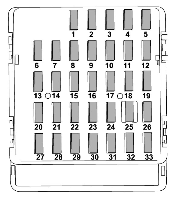
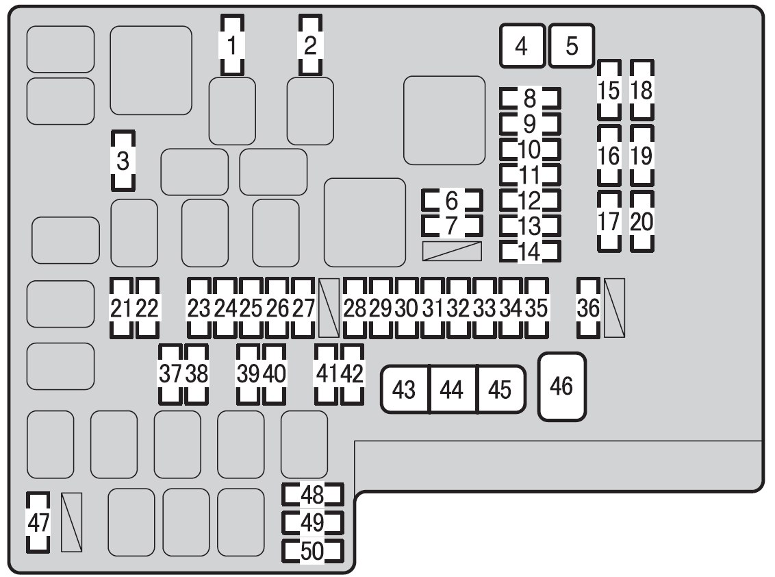
Fuse panel located behind the coin tray
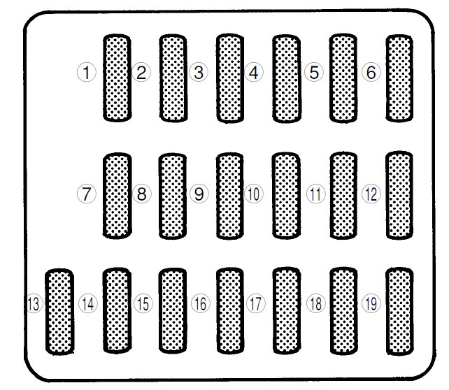
| Fuse | Ampere rating [A] | Circuit |
| 1 | 15 | Heater fan |
| 2 | 15 | Heater fan |
| 3 | 15 | Power door lock |
| 4 | 20 | Cigarette lighter, Remote controlled rear view mirrors |
| 5 | 10 | Tail light, Parking light |
| 6 | 15 | SRS airbag |
| 7 | 15 | Fog light |
| 8 | 20 | ABS solenoid |
| 9 | 15 | Radio, Clock |
| 10 | — | Empty |
| 11 | 15 | Engine ignition system, SRS airbag |
| 12 | 10 | Illumination brightness control |
| 13 | 15 | Wiper deicer |
| 14 | — | Empty |
| 15 | 20 | Windshield wiper and washer, Rear window wiper and washer |
| 16 | 20 | Brake light |
| 17 | 15 | Air conditioner |
| 18 | 15 | Backup light, Cruise control, ABS control |
| 19 | 20 | Rear accessory power socket, Seat heater |
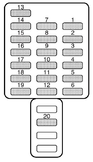
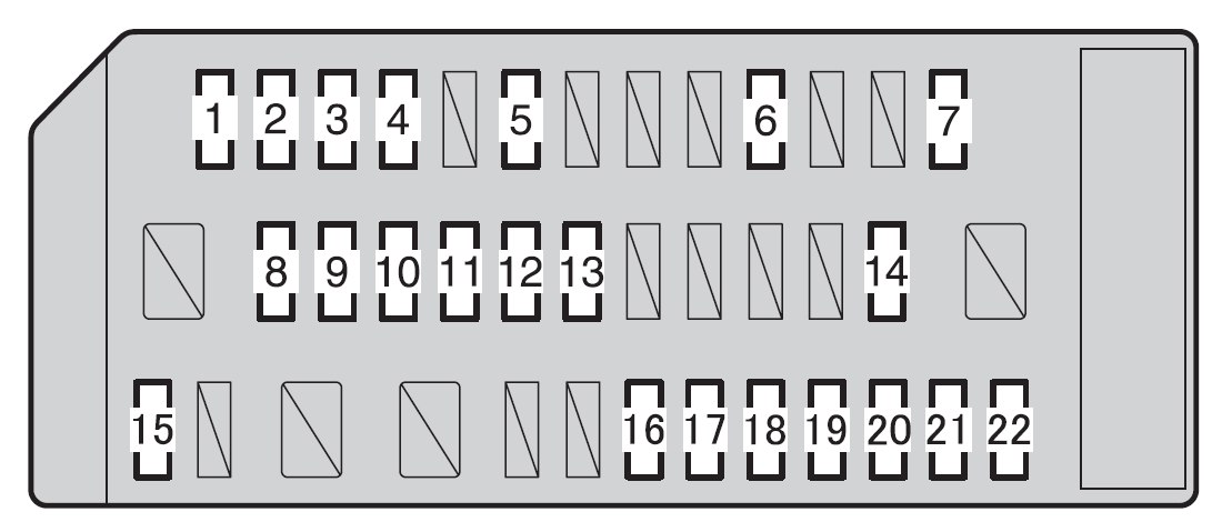
Fuse panel located in the engine compartment
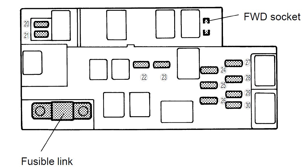
| Fuse | Ampere rating [A] | Power consumer |
| 20 | 20 | Radiator cooling fan (Main) |
| 21 | 20 | Radiator cooling fan (Sub) |
| 22 | 20 | Rear window defogger |
| 23 | 15 | Hazard warning flasher, Horn |
| 24 | 15 | Meter, SRS airbag system warning light |
| 25 | 10 | Automatic transmission control unit |
| 26 | 10 | Alternator |
| 27 | 15 | Headlight (right side) |
| 28 | 15 | Headlight (left side) |
| 29 | 20 | Lighting switch |
| 30 | 15 | Clock, Interior light |
WARNING: Terminal and harness assignments for individual connectors will vary depending on vehicle equipment level, model, and market.