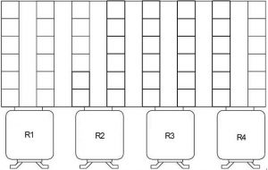
Kubota L4600 – fuse box diagram

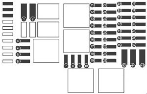
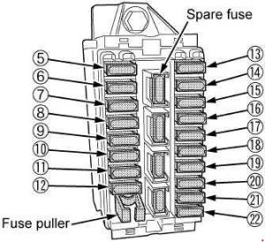
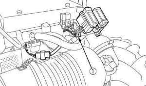
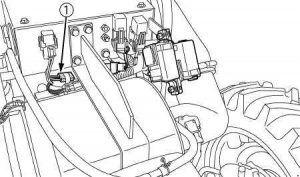
Kubota L4600 – fuse box diagram

Year of production:

Fuse box

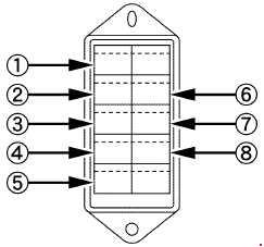
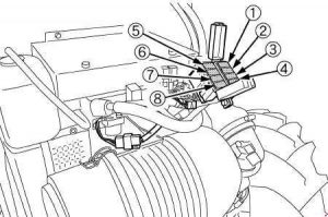
Kubota L4600 - fuse box diagram
Kubota L4600 – fuse box diagram
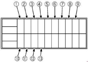
Number Ampere ratting [A] Protected circuit
1 15 Alternator
2 5 Head lights
3 5 Hazard
4 15 Panel
5 5 T/M Controller 1
6 5 Work light
7 10 Brake lamp switch
8 10 T/M Controller 2
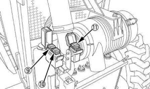
Kubota L4600 - fuse box diagram
Kubota L4600 – fuse box diagram
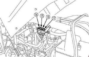
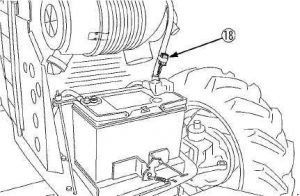
Number Ampere ratting [A] Protected circuit
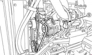
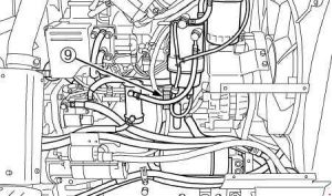
9 50 Key stop
10 40 Starter relay
11 40 Dome lamp

WARNING: Terminal and harness assignments for individual connectors will vary depending on vehicle equipment level, model, and market.

Kubota L3200, L3800 – fuse box diagram

Kubota L3200, L3800 – fuse box diagram

Year of production:

Fuse box

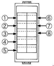
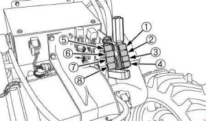
Kubota L3200, L3800 - fuse box diagram
Kubota L3200, L3800 – fuse box diagram
Number Ampere ratting [A] Protected circuit
1 15 Hazard
2 10 Work light
3 10 Panel
4 15 Head light
5 5 Key stop
6 5 Glow lamp
7 5 Starter relay
8 10 Brake lamp
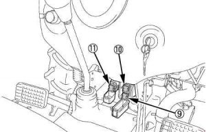
Kubota L3200, L3800 - fuse box diagram
Kubota L3200, L3800 – fuse box diagram
Number Ampere ratting [A] Protected circuit
9 40 Main
10 30 Key stop
11 40 Key switch

WARNING: Terminal and harness assignments for individual connectors will vary depending on vehicle equipment level, model, and market.

BMW 6 Series (E63, E64) (2004 – 2010) – fuse box diagram

BMW 6 Series (E63, E64) (2004 – 2010) – fuse box diagram

Years: 2004, 2005, 2006, 2007, 2008, 2009, 2010

Fuse box on the dashboard

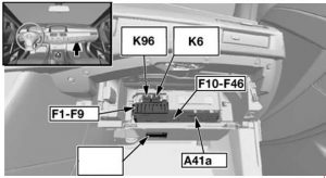
BMW 6-Series (E63 and E64) - fuse box diagram - dashboard
BMW 6-Series (E63 and E64) – fuse box diagram – dashboard


K6 – Relay, headlight washer, K93 – Relay, electronic damper control (as of 09.2005)
K96 – Fuel pump relay (M54 or N62), K9 – Power-saving relay, terminal 15 (as of 09.2005)
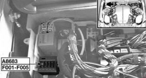
A41a – Fuse box

Fuse Ampere rating [A] Description
1 50 Dynamic stability  control (DSC)
2 60 Petrol: Secondary air pump relay
Diesel: Fuel heater
3 40 Blower output stage
4 40 up to 09.2005: Active steering
20 as of 09.2005: Power-saving relay, electronic  damper control
5 50 Light module
6 50 Light module
7 50 Car access system
30 Ignition / starter electronic
8 60 N62:
Integrated supply module (IVM)
N62 with SMG: 
Fuse carrier, engine electronics (F01: Hydraulic pump relay, SMG)
S85:
B+ potential distributor
DME relay
Fuse carrier, engine electronics (F01)
N52:
B+ potential distributor
DME control unit
DME relay
Fuse carrier, engine electronics:
F05: Relay, fuel injectors
F07: VVT relay
F08: Hydraulic pump relay, SMG
F010: Engine breather heating relay
9 60 Electric fan
10 30 up to 09.2005: Driver’s door module
as of 09.2005: Body-gateway module (LHD: window lift, driver’s side; RHD: window lift, passenger’s side)
11 5 Basic body module (central locking system, window lift, windscreen wiper relay)
12 30 up to 09.2005: Passenger’s door module
as of 09.2005: Body-gateway module (LHD: window lift, passenger’s side; RHD: window lift, driver’s side)
13 7,5 up to 09.2005: Instrument cluster control unit
30 VTG transfer case; as of 09.2005:  Control unit, transfer box
15 S85; as of 09.2005: Sequential manual transmission (SMG)
14 30 Seat module, front right (not semi-electric basic seat)
Switch, passenger’s seat adjustment (RHD; semi-electric basic seat)
Passenger’s lumbar support switch (RHD; semi-electric basic seat)
Switch, driver’s seat adjustment (LHD; semi-electric basic seat)
Driver’s lumbar support switch (LHD; semi-electric basic seat)
15 5 Car access system
16 30 Windscreen wiper relay
17 15 S85; up to 09.2005: Sequential manual transmission (SMG)
5 as of 09.2005: Steering column switch cluster
18 30 up to 09.2005: Relay, headlight washer
as of 09.2005: Body-gateway module
19 5 USA: Gear indicator lighting
S85: EDC Electronic damper control
20 20 SHZH independent/auxiliary heater: Heater Independent auxiliary heater
EDC Damper Control: Power-saving relay, electronic damper control
21 30 Seat module, front right (not semi-electric basic seat)
Switch, driver’s seat adjustment (RHD; semi-electric basic seat)
Driver’s lumbar support switch (RHD; semi-electric basic seat)
Switch, passenger’s seat adjustment (LHD; semi-electric basic seat)
Passenger’s lumbar support switch (LHD; semi-electric basic seat)
22 30 Basic body module (LHD: window lift rear, driver’s side; RHD: window lift rear, passenger’s side)
23 30 S85; as of 09.2005: Relay, electric vacuum pump
24 30 Basic body module (LHD: window lift rear, passenger’s side; RHD: window lift rear, driver’s side)
25 30 Dynamic stability control (DSC)
26 7,5 IHKA Basic: Heating/air conditioning system
20 as of 09.2005: Power-saving relay, terminal 15
27 30 Basic body module (central locking system)
28 20 Steering column  switch cluster
29 10 OBDII socket
Airbag
30 15 IHKA High: Heating/air conditioning system
20 Fuel pump output stage
Fuel pump relay
31 30 LHD: Seat module, front left (heated, active backrest-width adjustment, active seat)
RHD: Seat module, front right (heated, active backrest-width adjustment, active seat)
32 10 up to 09.2005: Dynamic drive
S85; up to 09.2005: Relay, electric vacuum pump
as of 09.2005:
Switch block, driver’s door
Electrochromic outside mirror, driver’s side
Electrochromic outside mirror, passenger’s side
33 30 Centre console switch centre
LHD: Seat module, front right (heated, active backrest-width adjustment, active seat)
RHD: Seat module, front left (heated, active backrest-width adjustment, active seat)
34 30 up to 09.2005: CCC/M-ASK
20 as of 09.2005: CCC/M-ASK
35 5 Navigation system
36 7,5 Comfort access control unit
Outer door handle electronic module, driver’s side
Outer door handle electronic module, passenger’s side
Electronic outer door handle module, rear left
Electronic outer door handle module, rear right
37 10 up to 09.2005:
TCU (telematics control unit)
ULF (universal charging & hands-free unit)
Eject box
5 09.2005-03.2007: 
TCU (telematics control unit)
ULF (universal charging & hands-free unit)
Eject box
as of 03.2007:
ULF-SBX interface box
TCU (telematics control unit)
ULF-SBX-H interface box High
USB hub
Eject box
38 10 up to 09.2005: CD changer
5 as of 09.2005: CD changer
39
40 10 DVD changer
41 5 as of 09.2005: Instrument cluster  control unit
42 15 S85: Sequential manual transmission (SMG)
43
44
45
46
Relay
K6 Relay, headlight washer
K93 Relay, electronic damper control (as of 09.2005)
K96  Fuel pump relay (M54 or N62)
K9 Power-saving relay, terminal 15 (as of 09.2005)
A41a Fuse box

Fuse box in rear

up to 09.2005

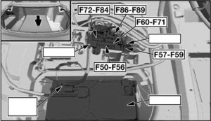
BMW 6-Series (E63 and E64) - fuse box diagram - in rear
BMW 6-Series (E63 and E64) – fuse box diagram – in rear

as of 09.2009

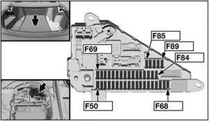
BMW 6-Series (E63 and E64) - fuse box diagram - in rear
BMW 6-Series (E63 and E64) – fuse box diagram – in rear
Fuse Ampere rating [A] Description
50 20 M54, N62: Fuel pump relay
N52, diesel: Fuel pump control (EKPS)
S85: Fuel pump output stage
30 as of 09.2005: Headlight washer pump
51 5 Siren and tilt alarm  sensor
Electrochromic interior rear view mirror
Microwave sensor, driver’s door
Microwave sensor, passenger’s door
Microwave sensor, rear left
Microwave sensor, rear right
52 10 Micro-power module
40 E64:
Relay, convertible top 1
Relay, convertible top 2
53 7,5 up to 09.2005: Automatic soft-close drive, boot lid/tailgate
09.2004-09.2005:
Comfort access control unit
Outer door handle electronic module, driver’s side
Outer door handle electronic module, passenger’s side
Electronic outer door handle module, rear left
Electronic outer door handle module, rear right
30 as of 09.2005:
Active backrest width adjustment, passenger
Active backrest width adjustment, driver
54 20 up to 09.2005: Power-saving relay, terminal 15
40 as of 09.2005: Rear window defogger
55 5 up to 09.2005: Rain/headlight sensor
40 as of 09.2005: Boot lid lift
56 5 as of 09.2005: Rain/headlight sensor
57 20 up to 09.2005: Micro-power module
5 IHKA Basic; as of 09.2005: Heating/air conditioning system
58 40 up to 09.2005: Rear window defogger
20 as of 09.2005: Rear wiper relay
57 5 Aerial tuner with remote control receiver
60 5 as of 09.2005: Rollover protection controller
61 20 up to 09.2005:
Front cigar lighter
Charging socket, glovebox
7,5 as of 09.2005: Cooler box
62 5 up to 09.2005: Power-saving relay, terminal 15
30 as of 09.2005:
    E64:
Relay for lowering rear window
Relay for raising rear window
63 5 up to 09.2005:
Electrochromic interior rear view mirror
Park distance control (PDC)
20 as of 09.2005: Independent auxiliary heater
64 10 up to 09.2005:
Rear compartment display
Central information display
Controller
15 IHKA High; as of 09.2005: Heating/air conditioning system
65 10 up to 09.2005:
Headset connection module
Head-up display
66 5 up to 09.2005:
Dynamic stability control (DSC)
    VTG Transfer case:
Dynamic stability control (DSC)
Control unit, transfer box
20 E63: Panorama glass roof
E64: Convertible top module
67 10 up to 03.2006:
Video module
Satellite receiver
20 as of 03.2006:
Automatic soft-close drive, passenger’s door (LHD)
Automatic soft-close drive, driver’s door (RHD)
Automatic soft-close drive, rear right
68 5 up to 03.2006:
Centre console switch centre
Switch, driver’s seat adjustment
Switch, passenger’s seat adjustment
20 as of 03.2006:
Automatic soft-close drive, driver’s door (LHD)
Automatic soft-close drive, passenger’s door (RHD)
Automatic soft-close drive, rear left
69 5 Park distance control (PDC)
70 5 up to 09.2005: Adaptive headlight
10 09.2005-03.2007: Active cruise control
as of 03.2007:
Active cruise control
Far-range sensor
Close-range sensor, right
Close-range sensor, left
71 20 up to 09.2005:
S85: Fuel pump output stage
30 as of 09.2005: Centre console switch centre
72 40 up to 09.2005:
   E64:
Relay, convertible top 1
Relay, convertible top 2
20 N62: Fuel pump relay
Diesel: Fuel pump control (EKPS)
73 30 up to 09.2005:
E63:
Relay for lowering rear window
Relay for raising rear window
Trailer module
09.2005-03.2007:
Hifi amplifier
40 as of 03.2007: Hifi amplifier
74 20 up to 09.2005: Trailer socket
10 as of 09.2005:
Centre console switch centre
Switch, driver’s seat adjustment
Switch, passenger’s seat adjustment
75 30 up to 09.2005: Control unit, trans-  fer box
10 as of 09.2005:
Satellite receiver
Digital tuner
Video module
76 40 up to 09.2005: Boot lid lift
10 as of 09.2005: Dynamic drive
77 5 up to 09.2005: Aerial tuner with remote control receive
10 as of 09.2005:
Head-up display
Headset connection module
78 5 as of 09.2005:
Dynamic stability control (DSC)
Control unit, transfer box
79 7,5 up to 09.2005: Electronic ride height control
10 as of 09.2005:
Central information display
Controller
80 30 up to 09.2005: HiFi amplifier
10 as of 09.2005:
Selector lever
Gear indicator lighting
Eject box
TCU (telematics control unit)
Compensator (mobile phone)
Fan, spare wheel well
Electronic night vision module
81 7,5 as of 09.2005: Electronic ride height control
82 20 up to 09.2005:
Luggage compartment socket outlet
Rear cigarette lighter
Socket outlet, rear
7,5 as of 09.2005: Tyre pressure control (RDC)
83 20 up to 09.2005:
E63: Panorama glass roof
    E64: Convertible top module
30 as of 09.2005:
Active backrest width adjustment, driver (LHD)
Active backrest width adjustment, passenger (RHD)
84 10 up to 09.2005: Active cruise control
15 as of 09.2005:
Transmission control
Sequential manual transmission (SMG)
85 7,5 as of 09.2005: Sequential manual transmission  (SMG)
86 15 up to 09.2005:
Transmission control
Sequential manual transmission (SMG)
40 as of 09.2005: Active steering
87 20 as of 09.2005:
Front cigar lighter
Charging socket,  glovebox
88 30 up to 09.2005: Centre console switch centre
20 as of 09.2005:
Luggage compartment socket outlet
Rear cigarette lighter
Socket outlet, rear
89 10 up to 09.2005:
Fan, MMC
Gear indicator lighting
Selector lever
Gear indicator lighting
Fan, spare wheel well
TCU (telematics control unit)
ULF (universal charging & hands-free unit)
Eject box
5 as of 09.2005:
Electrochromic interior rear view mirror
Power-saving relay, terminal 15


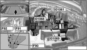
BMW 6-Series (E63 and E64) - fuse box diagram - in rear
BMW 6-Series (E63 and E64) – fuse box diagram – in rear
Fuse Ampere rating [A] Description
90 200 Fuse holder, front (fuse 1-33)
91 100 Diesel: DDE main relay
N62, TU: 
Integrated supply module (IVM)
VVT relay 1
VVT relay 2
Variable valve timing gear control unit
92 100 Electric auxiliary heater
Relay
I01061 Rear deffogger
I01068 Terminal 30G
I01069 Terminal 15

Fuse in engine compartment

M54

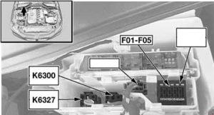
BMW 6-Series (E63 and E64) - fuse box diagram - engine compartment M54
BMW 6-Series (E63 and E64) – fuse box diagram – engine compartment M54
Number Realy
K6300 DME relay
K6327 Relay, fuel injectors

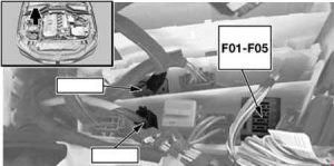
Diesel engine

BMW 6-Series (E63 and E64) - fuse box diagram - engine compartment (diesel engine)
BMW 6-Series (E63 and E64) – fuse box diagram – engine compartment (diesel engine)

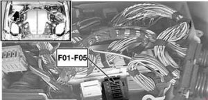
S85

BMW 6-Series (E63 and E64) - fuse box diagram - engine compartment (S85)
BMW 6-Series (E63 and E64) – fuse box diagram – engine compartment (S85)

N52

BMW 6-Series (E63 and E64) - fuse box diagram - engine compartment (N52)
BMW 6-Series (E63 and E64) – fuse box diagram – engine compartment (N52)
BMW 6-Series (E63 and E64) - fuse box diagram - engine compartment (N52)
BMW 6-Series (E63 and E64) – fuse box diagram – engine compartment (N52)
BMW 6-Series (E63 and E64) - fuse box diagram - engine compartment (N52)
BMW 6-Series (E63 and E64) – fuse box diagram – engine compartment (N52)
Number Realy
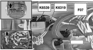
K6319 VVT relay
K6539 Engine breather heating relay
BMW 6-Series (E63 and E64) - fuse box diagram - engine compartment (N52)
BMW 6-Series (E63 and E64) – fuse box diagram – engine compartment (N52)
Fuse Ampere rating [A] Description
F01 30 N62: Hydraulic pump relay, SMG
N52: 
Interference suppression capacitor for ignition coils
Ignition coil (1, 2, 3, 4, 5, 6)
20 M57, TU: 
Hall-effect sensor, camshaft 1
Hot-film air mass meter
Rail pressure control valve
Volume control valve
Solenoid valve, boost pressure control
Heating, crankcase breather
S85:
Power-saving relay, terminal 15
Fuel injector (1, 2, 3, 4, 5, 6, 7, 8, 9, 10)
M57 TUTOP: 
Hall-effect sensor, camshaft 1
Hot-film air mass meter
Rail pressure control valve
Throttle valve
Turbine control valve
Volume control valve
Solenoid valve, boost pressure control
Heating, crankcase breather
F2 20 M57, TU:
Solenoid valve, exhaust gas recirculation
Oil level sensor
Electric changeover valve, swirl flaps
Preheating control unit
Electrical changeover valve, engine mount
Heating, crankcase breather
Boost pressure adjuster 1
Oxygen sensor be-fore catalytic converter
M57 TUTOP:
Solenoid valve, exhaust gas recirculation
Oil level sensor
Electric changeover valve, swirl flaps
Preheating control unit
Electrical changeover valve, engine mount
Oxygen sensor be-fore catalytic converter
Wastegate valve
Compressor bypass valve
S85:
Oxygen sensor be-fore catalytic converter
Oxygen sensor 2 be-fore catalytic converter
Oxygen sensor after catalytic converter
Oxygen sensor 2 after catalytic converter
30 N52:
Electric coolant pump
Thermostat, characteristic map cooling
Intake camshaft sensor
Exhaust camshaft sensor
VANOS solenoid valve, intake
VANOS solenoid valve, exhaust
F03 30 Diesel: Digital diesel electronics control unit
S85: DME control unit
20 N52:
DME control unit
Oil condition sensor
DISA actuator 1
DISA actuator 2
Fuel tank vent valve
Crankshaft sensor
Hot-film air mass meter
F04 10 Diesel:
Solenoid, radiator shutter
E-box fan
Exhaust flap
Brake air flap sensor, left
Brake air flap sensor, right
AUC sensor
S85: Ionic current control unit
30 N52:
Sequential manual transmission (SMG)
Oxygen sensor be-fore catalytic converter
Oxygen sensor 2 be-fore catalytic converter
Oxygen sensor after catalytic converter
Oxygen sensor 2 after catalytic converter
Crankshaft breather heating 1
F05 30 S85:
Pressure accumulator valve VANOS
Fuel tank vent valve 2
Intake camshaft sensor 2
Exhaust camshaft sensor 2
Air mass flow sensor 2
Idle actuator
Air mass flow sensor
Oil condition sensor
Intake camshaft sensor
Exhaust camshaft sensor
Secondary air pump valve
Charcoal filter valve
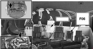
F06 10 N52; up to 03.2007:
Solenoid, radiator shutte
Secondary air pump relay
Exhaust flap
E-box fan
Diagnostic module for fuel tank leakage
Secondary air-hot-film air-mass meter
as of 03.2007:
Solenoid, radiator shutte
Secondary air pump relay
Exhaust flap
E-box fan
AUC sensor
Brake air flap sensor, left
Brake air flap sensor, right
Nitrogen oxide module
Diagnostic module for fuel tank leakage
Secondary air-hot-film air-mass meter
F07 40 N52: VVT relay
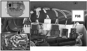
F08 30 N52: Hydraulic pump relay, SMG

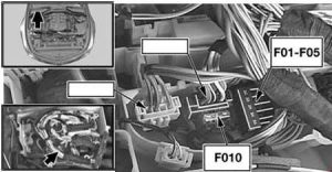
N62, TU

BMW 6-Series (E63 and E64) - fuse box diagram - engine compartment (N62, TU)
BMW 6-Series (E63 and E64) – fuse box diagram – engine compartment (N62, TU)

S85

BMW 6-Series (E63 and E64) - fuse box diagram - engine compartment (S85)
BMW 6-Series (E63 and E64) – fuse box diagram – engine compartment (S85)
Fuse Ampere rating [A] Description
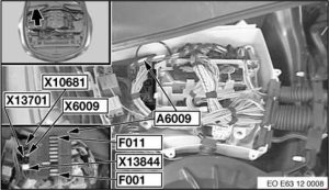
F001 30 N62:
DME control unit
Variable valve timing gear control unit
Fuel injector (5, 6, 7, 8)
Sequential manual transmission (SMG)
20 S85: Idle actuator, cylinder bank 1
F002 20 N62, TU:
DME control unit
Fuel tank vent valve
Intake camshaft sensor 2
Exhaust camshaft sensor 2
VANOS solenoid valve 2, intake
VANOS solenoid valve 2, exhaust
S85: Idle actuator, cylinder bank 2
F003 20 N62: Ignition coil (1, 2, 3, 4)
30 S85: Electric throttle valve, bank 1
F004 20 N62: Ignition coil (5, 6, 7, 8)
10 S85: Ionic current control unit 2
F005 30 N62, TU:
DME control unit
Crankshaft sensor
Hot-film air mass meter
Intake camshaft sensor
Exhaust camshaft sensor
Characteristic map thermostat
VANOS solenoid valve, intake
VANOS solenoid valve, exhaust
S85: Electric throttle valve, bank 2
F006 20 N62:
DME control unit
Fuel injector (1, 2, 3, 4)
F007 20 N62:
DME control unit
Sequential manual transmission (SMG)
F008 30 N62:
DME control unit
Oxygen sensor 2 after catalytic converter
Oxygen sensor before catalytic converter
Oxygen sensor 2 before catalytic converter
Oxygen sensor after catalytic converter
Oil quality sensor
F009 10 p to 03.2007:
Fuel pump relay
Exhaust flap
Solenoid, radiator shutter
E-box fan
Diagnostic module for fuel tank leakage
Secondary air pump relay
as of 03.2007:
Fuel pump relay
Exhaust flap
Solenoid, radiator shutter
E-box fan
Diagnostic module for fuel tank leakage
Secondary air pump relay
Brake air flap sensor, left
Brake air flap sensor, right
AUC sensor
F010 40 N62, TU: Variable valve timing gear control unit
5 N54: Engine breather heating relay
F011 40 N62, TU: Variable valve timing gear control unit
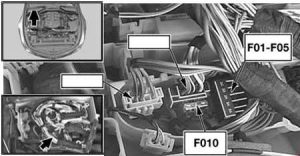
BMW 6-Series (E63 and E64) - fuse box diagram - engine compartment
BMW 6-Series (E63 and E64) – fuse box diagram – engine compartment


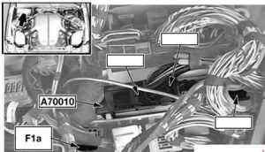
A70010 – Sequential manual transmission control unit

Fuse Ampere rating [A] Description
F1a 10 S85:
Solenoid, radiator shutter
E-box fan
Gear indicator lighting
Selector lever
Shift lock selector lever lock
Power-saving relay, electronic damper control
Bonnet switch, right
Bonnet switch, left
Rpm sensor, transmission main shaft
Relay, electric vacuum pump
Diagnostic module for fuel tank leakage
Secondary air-hot-film air-mass meter
Secondary air pump relay
A70010 Sequential manual transmission control unit

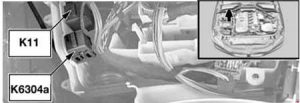
Windscreen Wiper Relay (K11), Secondary Air Pump Relay (K6304a)

BMW 6-Series (E63 and E64) - fuse box diagram - Windscreen Wiper Relay (K11) Secondary Air Pump Relay (K6304a)
BMW 6-Series (E63 and E64) – fuse box diagram – Windscreen Wiper Relay (K11) Secondary Air Pump Relay (K6304a)

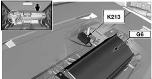
Relay, electric vacuum pump (K213)

BMW-6-Series (E63 and E64) - fuse box diagram - relay electric vacuum pump (K213)
BMW-6-Series (E63 and E64) – fuse box diagram – relay electric vacuum pump (K213)

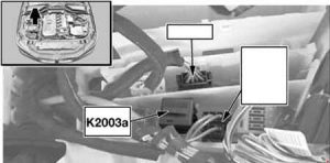
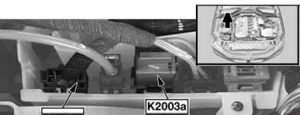
DDE main relay (K2003a)

M57 TU

BMW 6-Series (E63 and E64) - fuse box diagram - DDE main relay (K20030a) - M57 TU
BMW 6-Series (E63 and E64) – fuse box diagram – DDE main relay (K20030a) – M57 TU

M57, M57 TUTOP, M47 TU2

BMW 6-Series (E63 and E64) - fuse box diagram - DDE main relay (K20030a) - M57, M57 TUTOP, M47 TU2
BMW 6-Series (E63 and E64) – fuse box diagram – DDE main relay (K20030a) – M57, M57 TUTOP, M47 TU2

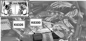
DDE relay (K6300)

S85

BMW 6-Series (E63 and E64) - fuse box diagram - DDE relay (K6300) - S85
BMW 6-Series (E63 and E64) – fuse box diagram – DDE relay (K6300) – S85
Number Description
K3626 Power-saving relay, terminal 15

N52

BMW 6-Series (E63 and E64) - fuse box diagram - DDE main relay (K20030a) - N52
BMW 6-Series (E63 and E64) – fuse box diagram – DDE main relay (K20030a) – N52

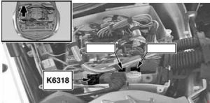
Hydraulic pump relay, SMG (K6318)

N62

BMW 6-Series (E63 and E64) - fuse box diagram - hydraulic pump relay, SMG (K6318) - N62
BMW 6-Series (E63 and E64) – fuse box diagram – hydraulic pump relay, SMG (K6318) – N62

S85

BMW 6-Series (E63 and E64) - fuse box diagram - hydraulic pump relay, SMG (K6318) - S85
BMW 6-Series (E63 and E64) – fuse box diagram – hydraulic pump relay, SMG (K6318) – S85
Number Description
K63831 Transmission fluid pump relay

WARNING: Terminal and harness assignments for individual connectors will vary depending on vehicle equipment level, model, and market.

Kubota Tractor M96SDTM – fuse box diagram

Kubota Tractor M96SDTM – fuse box diagram

Year of production:

Fuse box

Kubota Tractor M96SDTM - fuse box diagram
Kubota Tractor M96SDTM – fuse box diagram
Number Ampere ratting [A] Protected circuit
1 15 Flasher (Hazard)
2 15 Head Light
3 10 Tail Lamp, Horn
4 5 Engine, PTO. Alternator
5 10 T/M Control
6 5 Meter Panel, OPC, Buzzer
7 10 Turn Signal
8 15 AUX Power
9 5 Relay
10 15 Work Light RH (Front, F/S)
11 15 Work Light LH (Rear)
12 5 Meter Backup
13 10 Brake Lamp


Kubota Tractor M96SDTM - fuse box diagram
Kubota Tractor M96SDTM – fuse box diagram
Number Ampere ratting [A] Protected circuit
14 100 Charge
15 120 Heater
16 30 Main Key Switch
17 50 Head Light, Work Light


Kubota Tractor M96SDTM – fuse box diagram
Number Ampere ratting [A] Protected circuit
18 10 CRS Power [M108S]

WARNING: Terminal and harness assignments for individual connectors will vary depending on vehicle equipment level, model, and market.

Fiat Talento (2016 – 2018) – fuse box diagram

Fiat Talento (2016 – 2018) – fuse box diagram

Year of production: 2016, 2017, 2018

Fuse box diagram

Fiat Talento - fuse box diagram
Fiat Talento – fuse box diagram
Number Description
1 APC charger for vehicles with electronic key
2
3
4 + battery for vehicles with electronic key
5 Additional air conditioning
6 Additional cabin heating
7 Electric rearview mirrors, complementary central adaptation unit
8 Rear view mirror defroster
9 Radio, multi-media system, rear view mirror, diagnostic socket.
10 Predisposition for towing system
11 Timer battery, central passenger compartment unit
12 Right daytime running lights, front parking lights, right high beam, left low beam
13 Danger warning lights, direction indicators
14 Locking the opening parts
15 Left daytime running lights, rear parking lights, left high beam, right low beam
16 Licence plate light, front and rear fog lights
17 Alarms, acoustic warnings, light and windscreen wiper levers
18 Instrument panel
19 Heater
20 Rearscreen wipers, window washer pump, hom
21 General APC charger
22 Reversing lights
23 Stop switch
24 Injection, ignition
25 Air bag, steering wheel lock
26 Passenger’s electric window
27 Power steering
28 Brake lights
29 APC charger for vehicles with electronic key
30 General auxiliary
31 Cigar lighter, accessory socket
32 Heater
33 Stop lights, ABS, transponder
34 Interior lighting, air conditioning
35 Starter for vehicles with electronic key
36 Rear wiper
37 Electromagnetic warning
38 Additional socket in load compartment
39 Driver’s electric window motor
40 Auxiliary rear power socket
41 BCM starter
42 Heated seats
43 Tachograph
44 Front windscreen wiper
45 Heating and climate control

WARNING: Terminal and harness assignments for individual connectors will vary depending on vehicle equipment level, model, and market.

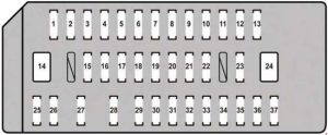
Lexus RX 350 (AL10) (2010 – 2015) – fuse box diagram

Lexus RX 350 (AL10) (2010 – 2015) – fuse box diagram

Year of production:2010, 2011, 2012, 2013, 2014, 2015

Passenger compartment fuse box

Lexus RX-350 (AL10) - fuse box diagram - passenger compartment
Lexus RX-350 (AL10) – fuse box diagram – passenger compartment
Fuse Ampere rating [A] Circuit protected
1 P/POINT 15 Power outlet
2 ECU-ACC 10 Navigation system, outside rear view mirror (2010-2012), multiplex communication system, multi-information display, head-up display, air conditioning system (2013-2015), audio system, (2013-2015)
3 CIG 15 Power outlet
4 RADIO NO. 2 7,5 Audio system, power outlet (2010-2012), navigation system (2013-2015)
5 GAUGE NO. 1 10 Emergency flashers, navigation system, head-up display , air conditioning system (2013-2015), charging system (2013-2015)
6 ECU-IG1 NO. 3 10 Outside rear view mirror, windshield wipers and washer, seat heaters, starter system, power outlet, moon roof, Automatic High Beam (2010-2012), air conditioning system (2013-2015)
7 ECU-IG1 NO.1 10 Multiplex communication system, electric power steering system, shift lock control system, tilt and telescopic steering, starter system, automatic transmission system, power back door, tire pressure warning system, vehicle stability control system (2013-2015), pre-collision system (2013-2015)
8 S/ROOF 30 Moon roof
9 FUEL OPN 7,5 Fuel filler door opener
10 PSB 30 Pre-collision seat belt
11 TI&TE 30 Tilt and telescopic steering system
12 DR LOCK 10 Power door lock system
13 FR FOG 15 2010-2012: Front log lights
FR FOG 7,5 2013-2015: Front log lights
14 P-SEAT LH 30 Power seat (left-side)
15 4WD 7,5 AWD system
16 INVERTER 20 2013-2015: Power outlet
17 RR FOG 7,5
18 D/LALTB 25 Multiplex communication system, power door lock system (2013-2015), power back door (2013-2015)
19 HEATER 10 2010-2012: Air conditioning system
ESP 10 2013-2015: Electric power steering system
20 ECU-IG1 NO. 2 10 2010-2012: Air conditioning system, multiport fuel injection system/sequential multiport fuel injection system, SRS airbag system, multi-information display
2013-2015: Intuitive parking assist, AWD system, pre-collision seat belt
21 PANEL 10 2010-2012: Switch illumination, navigation system, height control system, headlight cleaner, windshield wiper de-icer, seat heater, power back door, audio system, multi-information display, air conditioning system
2013-2015: Switch illumination, navigation system, audio system, multi-information display, air conditioning system, multiplex communication system automatic, transmission system
22 TAIL 10 Parking lights, side marker lights, tail lights, license plate lights, front fog lights, towing converter
23 AIR SUS 10 2010-2012: Electronically modulated air suspension system
24 P-SEAT RH 30 Power seat (right-side)
25 OBD 7,5 On-Board diagnosis
26 FR DOOR 25 Front power window (right-side), outside rear view mirror (2013-2015)
27 RR DOOR 25 Rear power window (right-side)
28 FL DOOR 25 Front power window (left-side), outside rear view mirror (2013-2015)
29 RL DOOR 25 Rear power window (left-side)
30 FR WASH 25 Windshield wipers and washer
31 RR WIP 15 Windshield wipers and washer
32 RR WASH 20 Windshield wipers and washer
33 FR WIP 30 Windshield wipers and washer
34 ECU IG2 10 2010-2012: Starter system, Intuitive parking assistsensor, AWD system
2013-2015: Multiport fuel injection system/sequential multiport fuel injection system, front passenger occupant classification system, SRS airbag system, stop lights, electronic controlled transmission, steering lock system
35 GAUGE NO. 2 7,5 2010-2012: Starter system
2013-2015: Gauge and meters
36 RH S-HTR 15 Seat heater (right-side)
37 LH S-HTR 15 Seat heater (left-side)


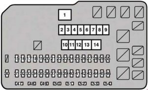
Engine compartment

Lexus RX-350 (AL10) - fuse box diagram - engine compartment
Lexus RX-350 (AL10) – fuse box diagram – engine compartment
Fuse Ampere rating [A] Circuit protected
1 RDI FAN NO. 1 80 Electric cooling fans
2 RR DEF 50 Rear window defogger
3 AIR SUS 50 2010-2012: Electronically modulated air suspension system
4 HTR 50 Air conditioning system
5 SPARE 30
6 SPARE 40
7 ABS NO.2 30 2010-2012: Anti-lock brake system
2013-2015: Vehicle stability control
8 H-LP CLN 30 Headlight cleaner
9 PBD 30 Power back door system
10 ST 30 Starter system
11 PD 50 2010-2012: Daytime running light system, A/F, H-LPRHHI.H-LP LH LO, H-LP RH LO, H-LP LH HI, HORN, S-HORN, multiplex communication system, multiport fuel injection system/ sequential multiport fuel injection system
2013-2015: A/F, H-LP RH HI, H-LP LH LO, H-LP RH LO, H-LP LH HI, HORN, SHORN
12 ABS NO.1 50 2010-2012: Anti-lock brake system
2013-2015: Vehicle stability control
13 EPS 60 Electric power steering system
14 ALT 140 2010-2012: FUEL OPN, DR LOCK, OBD, RR FOG, S/ROOF, 4WD, INVERTER, ECU IG1 NO. 1, ECU IG1 NO. 2, PANEL, GAUGE NO. 1
2013-2015: IG1 MAIN, TOWING BATT, DEICER, TOWING, STOP, RDI FAN NO. 1, FILTER, RR DEF, AIR SUS, HEATER, ABS NO. 2, H-LP CLN, PBD, ECU-IG1 NO. 1, ECU-IG1 NO. 3, GAUGE NO. 1, ECU-IG1 NO. 2, EPS, FR WIP, RR WIP, FR WASH, RR WASH, RH S-HTR, LH S-HTR, TAIL, PANEL, D/L ALT B, FR FOG, FR DOOR, FL DOOR, RR DOOR, RL DOOR, PSB, P-SEAT LH, P-SEAT RH, TI&TE, FUEL OPN, DR LOCK, OBD, RR FOG, S/ROOF, 4WD, INVERTER, ECU-ACC, P/POINT, CIG, RADIO NO. 2
15 AMP1 30 Audio system
16 EFI MAIN 30 2010-2012: Multiport fuel injection system/ sequential multiport fuel injection system, EFI NO. 1, EFI NO. 2
2013-2015: Multiport fuel injection system/sequential multiport fuel injection system, electronic controlled transmission, EFI NO. 1, EFI NO. 2, F/PMP
17 AMP2 30 Audio system
18 IG2 30 2010-2012: Starter system, IGN, GAUGE NO. 2, ECU IG NO. 2
2013-2015: IGN, GAUGE NO. 2, ECU IG 2
19 IP JB 25 Power door lock system
20 STR LOCK 20 Starter system
21 RAD NO. 3 15 2010-2012: Meters and gauges lights, instrument panel lights, navigation system, audio system, rear seat entertainment system
2013-2015: Meters and gauges, navigation system, audio system
22 HAZ 15 Emergency flashers
23 ETCS 10 Multiport fuel injection system/ sequential multiport fuel injection system
24 RAD NO. 1 10 Audio system, navigation system (2013-2015)
25 AM2 7,5 Starting system
26 ECU-BNO. 2 7,5 2010-2012: Air conditioning system, front passenger occupant classification system, starter system
2013-2015: Air conditioning system, front passenger occupant classification system, audio system, vehicle stability control system, power windows
27 MAYDAY/TEL 7,5 2013-2015: MAYDAY/TEL
28 IMMOBI 7,5 2013-2015: IMMOBI
29 ALT-S 7,5 Charging system
30 IGN 10 2010-2012: Starter system, multiport fuel injection system/sequential multiport fuel injection system
2013-2015: Multiport fuel injection system/sequential multiport fuel injection system
31 DOME 10 Vanity mirror lights, luggage compartment lights, interior lights, personal lights, door courtesy lights (2013-2015), footwell lights (2013-2015), scuff lights (2013-2015)
32 ECU-B NO. 1 7,5 2010-2012: Interior lights, personal lights, tilt and telescopic steering, multiplex communication system, meters and gauges, power window, driving position memory system, power seats, power back door, head-up display, starter system, air conditioning system, power door lock system
ECU-B NO. 1 10 2013-2015: Tilt and telescopic steering, multiplex communication system, meters and gauges, driving position memory, power seats, power back door, headup display, starter system, outside rear view mirror, steering sensor, garage door opener
33 EFI NO. 1 10 Multiport fuel injection system/ sequential multiport fuel injection system, electronic controlled transmission (2013-2015)
34 WIP-S 7,5 2010-2012: Windshield wipers and washer
2013-2015: Cruise control
35 AFS 7,5 2010-2012: Adaptive front-lighting system
ECU-IG1 NO. 4 10 2013-2015: Air conditioning system, rear window defogger, vehicle stability control system, electric cooling fans
36 BK/UP LP 7,5 Buck-up lights
37 HEATER NO. 2 7,5 2010-2012: Air conditioning system, AWD system
ECU-IG1 NO. 5 7,5 2013-2015: Air conditioning system
38 ECU IG1 10 2010-2012: Adaptive front-lighting system, headlight cleaner, cooling fan, cruise control, electronically modulated air suspension system, vehicle stability control, vehicle dynamics integrated management
ECU-IG1 NO. 6 10 2013-2015: Head light cleaner, cruise control, vehicle stability control, air conditioning system, Blind Spot Monitor
39 EFI NO.2 10 Multiport fuel injection system/sequential multiport fuel injection system
40 F/PUMP 15 Multiport fuel injection system/sequential multiport fuel injection system
41 DEICER 25 Windshield wipers and washer
42 STOP 7,5 2010-2012: Vehicle stability control, vehicle dynamics integrated management, high mounted stoplight
2013-2015: Vehicle stability control, vehicle dynamics integrated management, stop lights, electronic controlled transmission, multiport fuel injection system/sequential multiport fuel injection system, shift lock control system, starter system
43 TOWING BATT 20 Trailer battery
44 TOWING 30 Trailer lights
45 FILTER 10 2010-2012: Condenser
46 IG1 MAIN 30 2010-2012: ECU IG1, BK/UPLP, HEATER NO. 2,AFS
2013-2015: ECU-IG1 NO. 6, BK/UP LP, ECU IG1 NO. 5, ECU-IG1 NO. 4
47 H-LP RH HI 15 Right-hand headlight (high beam)
48 H-LP LH HI 15 Left-hand headlight (high beam)
49 BIXENON 10 2010-2012: Discharge headlight
50 H-LP RH LO 15 Right-hand headlight (low beam)
51 H-LP LH LO 15 Left-hand headlight (low beam)
52 HORN 10 Horn
53 A/F 20 Multiport fuel injection system/ sequential multiport fuel injection system
54 S-HORN 7,5 Security horn
55 DRL 7,5 Daytime running light system

WARNING: Terminal and harness assignments for individual connectors will vary depending on vehicle equipment level, model, and market.

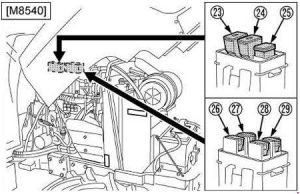
Kubota Power Krawler M8540 Narrow – fuse box diagram

Kubota Power Krawler M8540 Narrow – fuse box diagram

Year of production:

Fuse box

Kubota Power Krawler M8540 Narrow - fuse box diagram
Kubota Power Krawler M8540 Narrow – fuse box diagram
Number Ampere ratting [A] Protected circuit
1 20 Side Window Defogger
2 20 Rear Window Defogger
3 10 4WD / Bi-Speed Turn
4 10 45WD brake
5 15 Work Light (Rear)
6 15 Work Light (Front)
7 15 Cigarette Lighter
8 20 Air Conditioner (Fan Motor)
9 10 Air Conditioner (Compressor)
10 15 Work Light (Front, Side)
11 15 Auxiliary Power
12 5 Starter Relay
13 5 Radio
14 5 Air Conditioner (Control)
15 15 Wiper
16 5 Alternator, Engine, PTO, Heater
17 5 Meter Panel, OPC
18 10 Turn Signal, Stop Lamp
19 10 Meter, Radio (Back Up)
20 20 Head Light, Position Lamp
21 20 Flasher (Hazard)
22 20 Spare Fuse
Kubota Power Krawler M8540 Narrow - fuse box diagram
Kubota Power Krawler M8540 Narrow – fuse box diagram
Number Ampere ratting [A] Protected circuit
23 50 Head Light, Hazard
24 50 Air Heater
25 100 Charge
26 30 Electrical Outlet
27 40 Air Conditioner
28 30 Work Light, Fuel Cut Solenoid
29 30 Key Switch

WARNING: Terminal and harness assignments for individual connectors will vary depending on vehicle equipment level, model, and market.

Mercedes-Benz B-Class W245 (2006 – 2011)  – fuse box diagram

Mercedes-Benz B-Class W245 (2006 – 2011)  – fuse box diagram

Year of production: 2006, 2007, 2008, 2009, 2010, 2011

Fuse box in the front-passenger footwell

Mercedes-Benz B-Class W245 - fuse box diagram - in the front passenger-footwell
Mercedes-Benz B-Class W245 – fuse box diagram – in the front passenger-footwell
Number Fused function Ampere ratting [A]
1 2006-2008: Stop light switch 10
Light and vision package (2006-2008): Stop light switch
2009-2011: Stop light switch
5
2 Heated rear window 25
3 nstrument cluster
EIS [EZS] control unit
7,5
4 EIS [EZS] control unit
Electric steering lock control unit
15
5 Automatic air conditioning and Comfort automatic air conditioning:HEAT control and operating unit
Automatic air conditioning: AAC [KLA] control and operating unit
Comfort automatic air conditioning: Comfort AAC [KLA] control and operating unit
7,5
6 Left fanfare horn
Right fanfare horn
15
7 Fuel pump relay 25
8 Overhead control panel control unit 25
9 ESP and BAS control unit 40
10 Blower regulator/interior wiring harness connector 40
11 Valid for engine 266: Circuit 87 relay, engine 30
Valid for engine 640: Circuit 87 relay, engine 40
12 Steering column module
Multifunction steering wheel (2006-2008)
5
13 Left front door control unit 25
14 Right front door control unit 25
15 ESP and BAS control unit 25
16 Data link connector
Parktronic system (PTS) control unit (2006-2008)
10
17 Rotary light switch 5
18 Valid for transmission 711, 716: Backup lamp switch 7,5
19 Micromechanical turn rate sensor AY pickup 5
20 Restraint systems control unit 7,5
21 Starter relay 30
22 Instrument cluster 7,5
23 2006-2008: Washer nozzle heating 7,5
Valid for engine 640 as of 1.9.08: Fuel filter condensation sensor with heating element 20
24 Electric power steering (ES) control unit 7,5
25 Stop light switch
ESp and BAS control unit
7,5
26 Valid for transmission 722: Electronic selector lever module control unit 7,5
27 V10alid for transmission 722: CVT (continuously variable automatic transmission) control unit 7,5
28 Rotary light switch 5
29 SAM control unit 30
30 Circuit 87F relay 25
31 2006-2008:
Central gateway control unit (vehicles up to 30.11.05)
Rotary light switch
2009-2011:
Automatic light switch daylight sensor
Rain/light sensor
5
32 Valid for engine 266: ME-SFI [ME] control unit 7,5
33 Radio
Radio and navigation unit
COMAND operating, display and control unit (Japan)
15
34 Left rear door control unit 25
35 Right rear door control unit 25
36 2006-2008:
Cell phone separation point
Trailer control unit
7,5
2009-2011:
Trailer control unit
PTS control unit
10
37 Restraint systems control unit
Front passenger seat occupied recognition sensor
Front passenger seat occupied and child seat recognition sensor
7,5
38 Front cigar lighter with ashtray illumination 25
39 Wiper motor 25
40 Louvered sunroof: Overhead control panel control unit 7,5
Lamella roof: Overhead control panel control unit 25
41 Liftgate wiper motor 15
42 Glove compartment illumination with switch
Left and right vanity mirrors illumination
Footwell illumination switch (driving school package)
Pedal operation monitor switch (driving school package)
VICS+ETC voltage supply separation point (Japan)
7,5
43 Valid for engine 266:
Terminal 87M1 e connector sleeve
Bivalent natural gas drive (2009-2011):
Terminal 87M1e connector sleeve
15
Valid for engine 640:
Terminal 87M1e connector sleeve
7,5
44 Valid for engine 266:
Terminal 87M2e connector sleeve
15
Valid for engine 640:
Terminal 87M2e connector sleeve
20
45 Valid for engine 640:
CDI control unit
25
46 2006-2008:
Telephone control unit, (Japan)
E-net compensator
Universal Portable CTeL Interface (UPCI [UHI]) control unit
7,5
2009-2011: Bass module speaker (Japan) 25
2009-2011: Amplifier for sound system 40
47 Telephone control unit, (Japan)
Universal Portable CTEL Interface (UPCI [UHI]) control unit
Cell phone separation point
Voice control system (VCS [SBS]) control unit
7,5
48 ATA [EDW]/tow-away protection/interior protection control unit
Alarm signal horn with additional battery
7,5
49 Upper control panel control unit
Left front seat heated cushion (2006-2008)
Left front backrest heated cushion (2006-2008)
Right front seat cushion heater element (2006-2008)
Right front backrest seat cushion heater element (2006-2008)
25
50 2006-2008:
CD changer
VICS+ETC voltage supply separation point (Japan)
2009-2011:
Media interface control unit
Digital TV tuner
Digital Audio Broadcasting control unit
7,5
Valid for government vehicles (2009-2011):
Roof light bar
Circuit 30 connector sleeve
30
51 Canada (2009-2011): Weight Sensing System (WSS) control unit
Valid for government vehicles (2009-2011): Special signal system control panel
10
52 VICS+ETC voltage supply separation point (Japan) (vehicles up to 31.5.0 5
Spare (vehicles as of 1.6.06) 7,5
Emergency call system control unit (USA) (vehicles up to 31.5.06) 7,5
53 Rear cigar lighter with ashtray illumination
Interior socket
30
54 Amplifier for sound system
Bass module speaker
25
Valid for government vehicles (2009-2011): 2-pin 12V socket 15
55 Left front lamp unit (Bi-xenon)
Right front lamp unit (Bi-xenon)
7,5
Left front lamp unit (Hi-xenon) 10
56 Spare 10
Right front lamp unit (Hi-xenon) 10
57 2009-2011: Trailer hitch socket (13-pin) 15
2006-2008: Audio gateway control unit (Japan) 25
2006-2008:
SDAR control unit
Emergency call system control unit (USA)
7,5
58 Trailer control unit 25
59 Trailer control unit (vehicles up to 31.5.05)
Trailer hitch socket (13-pin) (vehicles as of 1.6.05)
20
60 Driver seat connector block 20
61 Front passenger seat connector block 20
62 Circuit 15 relay (2) (SA: xenon, cell phone) 25
63 Spare (vehicles up to 31.5.05)
Valid for government vehicles (2009-2011): Roof light bar 25
Emergency call system control unit (USA) (vehicles as of 1.6.05)
SDAR control unit (vehicles as of 1.6.05)
7,5
64 Valid for engine 266: Air pump relay 40
Valid for engine 640:
Engine wiring harness/engine compartment connector (2006-2008)
Glow time output stage (2009-2011)
80
65 Electric power steering (ES) control unit 80
66 SAM control unit 60
67 Circuit 15R relay (2) (SE) 50
68 Valid for engine 266.920 and engine 266.940 with transmission 722:
AAC with integrated control additional fan motor
50
Valid for engine 640.940, 640.941, 266.960, 266.980 and for engine 266.920, 266.940 with (Trailer hitch):
AAC with integrated control additional fan motor
60
69 Circuit 15R relay (1) 50
70 Circuit 15 relay (1) 60
71 Valid for engine 640: PTC heater booster 150
72 2006-2008: Circuit 30 connector sleeve
2009-2011:
Special vehicle multifunction control unit (SVMCU [MSS]) (Taxi)
Valid for government vehicles:
Fuse 7
Fuse 10
60
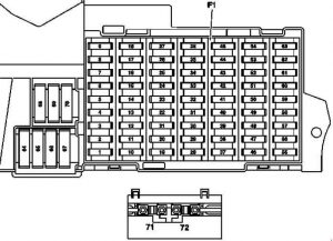
Mercedes-Benz B-Class W245 - fuse box diagram - in the front passenger-footwell
Mercedes-Benz B-Class W245 – fuse box diagram – in the front passenger-footwell
Number Fuse function Ampere ratting [A]
80 Special vehicle multifunction control unit 30
81 Special vehicle multifunction control unit 30
82 Special vehicle multifunction control unit 30
83 Special vehicle multifunction control unit 30
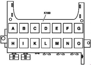
Relay
A Circuit 15R relay (2) (SA)
B Circuit 15R relay (1)
C Fanfare horn relay
D Heated rear window relay
E Wiper stage 1/2 relay
F Wiper ON/OFF relay
G Circuit 15 relay (1)
H Backup relay
I Valid for engine 266: Air pump relay
K Fuel pump relay
L Engine circuit 87 relay
M Starter relay
N Circuit 87F relay
O Circuit 15 relay (2) (SA: xenon, cell phone)

WARNING: Terminal and harness assignments for individual connectors will vary depending on vehicle equipment level, model, and market.

Kubota M100GX, M110GX, M126GX, M135GX – fuse box diagram

Kubota M100GX, M110GX, M126GX, M135GX – fuse box diagram

Year of production:

Fuse box diagram

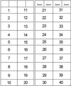
Kubota M100GX, M110GX, M126GX, M135GX - fuse box diagram
Kubota M100GX, M110GX, M126GX, M135GX – fuse box diagram
Number Ampere ratting [A] Description
1
2 10 ECU (Suspension)
3 5 ECU (Switch)
4 20 Defogger
5
6 10 Brake lamp
7 5 Radio
8 5 Air conditioner (Fan control)
9 15 Wiper
10 5 Starter relay
11
12 5 Switch (Transmission control)
13 5 Switch (Hitch control)
14 10 ECU (Main)
15 5 Main meter
16 5 4WD, Bi-speed, Differential lock
17 5 Engine control, PTO valve
18 10 Turn signal
19 15 Loader power aux socket
20 5 LCD monitor
21 15 Work light (Cabin side)
22 15 Work light (Front upper)
23
24
25 10 Option lamp
26 15 Work light (Rear)
27 10 Work light (Bonnet)
28 15 Seat compressor
29 15 Cigarette socket
30 15 Work light (Option)
31
32 15 Head lamp
33 30 Air conditioner fan motor
34 10 Air conditioner compressor
35 15 Tail lamp
36 15 Hazard
37 10 Dome light, Radio
38 5 Horn
39 5 Glow relay
40 5 Back up (ECU, Meter)

M100GX, M110GX

Kubota M100GX, M110GX - fuse box diagram
Kubota M100GX, M110GX – fuse box diagram

M126GX, M135GX

Kubota M126GX, M135GX - fuse box diagram
Kubota M126GX, M135GX – fuse box diagram
Number Ampere ratting [A] Description
1 20 CRS POWER

M100GX, M110GX

Kubota M100GX, M110GX - fuse box diagram
Kubota M100GX, M110GX – fuse box diagram

M126GX, M135GX

Kubota M126GX, M135GX - fuse box diagram
Kubota M126GX, M135GX – fuse box diagram
Number Ampere ratting [A] Description
1 40 Defogger
2 30 Electrical outlet
3 40 Work light (Rear)
4 120 M100GX, M110GX: Engine preheat
40 M126GX, M135GX:
Work light (Hood)
Head lamp
5 40 M100GX, M110GX:
Work light (Hood)
Head lamp
60 M126GX, M135GX: Engine preheat
6 40 Compressor
7 30 Hazard
8 30 Main key switch

M100GX, M110GX

Kubota M100GX, M110GX - fuse box diagram
Kubota M100GX, M110GX – fuse box diagram

M126GX, M135GX

Kubota M126GX, M135GX - fuse box diagram
Kubota M126GX, M135GX – fuse box diagram
Number Ampere ratting [A] Description
9 140 Alternator

WARNING: Terminal and harness assignments for individual connectors will vary depending on vehicle equipment level, model, and market.

BMW 3 Series E36 and E35/5 (1990 – 2000) – fuse box diagram

BMW 3 Series E36 and E35/5 (1990 – 2000) – fuse box diagram

Years: 1990, 1991, 1992, 1993 ,1994, 1995,

Front power distribution box

BMW 3 Series E36 and E35/5 - fuse box diagram - front box distribution box
BMW 3 Series E36 and E35/5 – fuse box diagram – front box distribution box
Fuse Ampere rating [A] Description
1 30 Power tilt/slide sunroof (SHD)
2 15 as of 9/93: Trailer coupling
5 as of 9/96: Engine control system
3 30 Rear wipe/wash interval control unit (Touring, Compact)
Headlight washer system (SRA)
Radio/HiFi (9/94 to 8/95)
4 15 Unloader relay terminal 15 (Heated seats)
5 30 Passenger’s seat adjustment switch
6 20 Rear defogger relay
30 Rear defogger relay
7 5 Electronic gear indicator
Central locking switch
Driver’s door lock switch
Central locking (ZV) drive driver’s door
Central locking module (ZVM)
Central locking (ZV) drive passenger’s door
Passenger’s door lock switch
Control unit, remote control
Rear lid lock relay
Central locking drive rear lid (Touring)
Rear lid microswitch (mechanical convertible soft top)
Convertible soft top flap lock
Convertible soft top module
Anti-theft control module (Alpine)
8 15 Horn relay
Anti-theft control module (Alpine)
9 20 Radio
Hifi amplifier
Subwoofer
CD changer (to 8/93)
Unloader relay terminal R (to 8/92)
10 30 Antilock brake system (ABS)
Automatic stability control (ASC)
11 7,5 without CCM: Left low beam light
with CCM: Check control module
12 7,5 without CCM: Right low beam light
with CCM: Check control module
13 5 Comfort relay (two–door model)
14 30 Driver’s side power window module (to 8/93)
Passenger’s side power window module (to 8/93)
ZKE control unit (ZKE IV; as of 9/93)
15 15 Left fog light
Right fog light
Instrument cluster
7,5 Left fog light
Right fog light
Instrument cluster
16 5 A/C compressor relay
Auxiliary fan stage 1 relay (normal speed relay)
Auxiliary fan stage 2 relay (high speed relay)
17 10 without CCM: Fog light switch (Rear fog light switch)
7,5 with CCM: Fog light switch (Rear fog light switch)
18 15 Fuel pump
19 15 to 8/92: Park heating/ventilation relay box
30 as of 8/93: Relay module
20 30 to 8/92: Blower switch
as of 9/92:
   without park ventilation: Heating blower relay
   with park ventilation:
Heating blower relay
Independent ventilation relay
21 5 Antilock brake system (ABS)
Automatic stability control (ASC)
22 5 Light switch
Daytime running lights coding diode
23 5 Combination switch (turn indicator/low beam selector)
Instrument cluster
Thermal switch (LA Japan)
ABS control unit
Rear defogger relay
Multi–function clock / On–board display / On–board computer
Unloader relay terminal 15
with IHKA: Automatic climate control unit
with heating control:
Water valves
Temperature regulator
24 10 Thermal switch, heated jets
Rollover sensor
Mirror control unit
Parking aid control unit
25 5 Light switch
Day light relay module (as of 9/97)
High beam relay (9/94 to 8/97)
Low beam relay (9/92 to 8/94)
Left park light relay (9/93 to 8/94)
Right park light/license plate light relay (9/93 to 8/94)
26 15 to 8/92:
Program switch
Auxiliary connector (US)
Automatic transmission range switch
Diagnostic connector
Reversing light switch (without EGS)
10 as of 9/92:
Automatic transmission range switch
Program switch
Fuel heating (diesel)
Alternator cut–out relay (diesel)
Diagnostic connector
Oil level switch, thermal
Oxygen sensor and air pump relays
Reversing light switch
SMG control unit
Hydraulic pump relay
Hydraulic unit
Starter immobilization relay
Throttle flap heater
27 5 Instrument cluster
28 5 with EGS: Automatic transmission range switch
with SMG:
SMG control unit
Electronic gear indicator
Gear indicator, centre console
29 7,5 Left high beam
30 7,5 Right high beam
31 5 Instrument cluster
On–board display / Multi–function clock
On–board computer
Analogue clock
Chime module
Electronic immobiliser control unit (EWS II; as of 9/94)
Antitheft (DWA) LED
With IHKA:
Water valves
Automatic climate control unit
With IHKR:
IHKR control panel
Integrated climate regulation control module
32 30 Front cigar lighter
Reading lights relay
33 10 Ignition switch (as of 9/93)
Charge socket
Light switch
CD changer (as of 9/93)
Cellular telephone
Door lock heating relay
Luggage compartment light
Rear compartment interior light, centre (Touring)
Right trunk light assembly (Compact)
Interior light, right rear (with reading light)
Interior light, left rear (with reading light)
Interior/reading lamp, front (with ZKE)
ZKE control unit (as of 9/93)
Front left footwell light (Front right footwell light)
Left parking light relay
Driver’s side power window module (to 8/93)
34 15 Hazard flasher relay
Crash alarm sensor (with crash alarm sensor)
35 25 with ZVM: Central locking module (ZVM)
with ZKE: ZKE control unit
36 30 Wipe–wash module (Low II) / Wipe/wash module
37 10 Light switch
Right parking light/licence plate light relay
38 30 Antilock brake system (ABS)
Automatic stability control (ASC)
39 7,5 A/C compressor relay
40 30 Driver’s seat adjustment switch
Driver’s lumbar support switch
41 30 Auxiliary fan stage 1 relay (low; only diesel)
Auxiliary fan stage 2 relay (high)
42 7,5 Electronic seat control
Driver’s side impact sensor
Passenger’s side impact sensor
Rollover sensor
Airbag diagnostic module
Driver’s seat belt buckle switch
43 5 Interior light, right rear
Interior light, left rear
Top Hifi switch
Central locking module (ZVM)
ZKE control unit
Spatial sound relay
Passenger’s make–up mirror light
Driver’s make–up mirror light
Interior/reading lamp, front
Convertible soft top module
Control unit, remote control
Cellular telephone
Reading lights relay
Anti-theft control module (Alpine)
44 15 Wipe–wash module (Low II)
Wipe/wash module
Rear wipe/wash interval control unit (Touring, Compact)
Windscreen wiper switch (Touring, Compact)
Radio
Glovebox light/switch
Twin relay module (up to 8/95)
Unloader relay terminal R (up to 8/92)
45 7,5 Check control module
Transmit/receive module (EWS II; as of 9/95)
Starter immobilization switch (as of 9/96)
On–board computer / Multi–function clock / On–board display
Wiper relay (up to 8/95)
Wiper motor relay (up to 8/95)
46 15 Clutch switch
Instrument cluster
Brake light switch
Cruise control module
Cruise control switch
Data link connector (as of 9/95)
Board computer (BC-low)
Relay
R1 Fuel pump relay
Oxygen sensor and air pump relays (M3)
Secondary air pump relay
Engine control module relay
Alternator cut–out relay (diesel)
R2 Engine control module relay
Fuel pump relay
R3 Oxygen sensor relay
EKP and start detector relay
Wiper motor relay
Engine control module relay
Secondary air pump relay
Delivery pump relay (diesel)
R4 Horn relay
R5 Fog light relay
R6 High beam relay (to 8/93)
Low beam relay (as of 9/93)
R7 Low beam relay (to 8/93)
High beam relay (as of 9/93)
Secondary air pump relay
R8 Hazard flasher relay
R9 Blower relay
R10 Rear defogger relay
R11 ABS relay
R12 ABS pump motor relay
ABS pump motor relay, timed
R13 Auxiliary fan stage 2 relay (high speed)
R14 A/C compressor relay
R15 Auxiliary fan stage 1 relay (low speed)

Relay carrier under LH side of dash

BMW 3 Series E36 and E35/5 - fuse box diagram - relay carrier under LH side of dash
BMW 3 Series E36 and E35/5 – fuse box diagram – relay carrier under LH side of dash
Fuse Ampere rating [A] Description
48 40 Auxiliary fan stage 2 relay (high speed)
50 5 Exhaust gas flap valve
Carbon canister valve
Relay
R1 Independent ventilation relay
R2 Twin relay (up to 8/95)
R3 Crash alarm sensor
R4 Headlight/foglight cleaning module (SRA) (up to 8/95)
High beam relay
Day running ligth relay
R5 Comfort relay
Folding sunroof comfort relay
R6 Unloader relay terminal R (up to 8/92)

Connector strip under LH side of dash

BMW 3 Series E36 and E35/5 - fuse box diagram - connector strip under LH side of dash
BMW 3 Series E36 and E35/5 – fuse box diagram – connector strip under LH side of dash
Fuse Ampere rating [A] Description
47 158 Horn relay (Alpine)
On-board computer
Anti-theft control module (Alpine)
Relay
R1 Unloader relay terminal 15
Horn relay (Compact)
R2 Rear lights relay
Wiper relay (up to 8/95)
R3 Wiper motor relay (up to 8/95)
R4 Hinged window relay
Starter relay (up to 8/94)
Starter immobilization relay (9/93 to 9/94)

Connector strip under RH side of dash

BMW 3 Series E36 and E35/5 - fuse box diagram - connector strip under RH side of dash
BMW 3 Series E36 and E35/5 – fuse box diagram – connector strip under RH side of dash
Number Realy
R1 Right parking light/licence plate light relay
R2 Left parking light relay
Thermal switch (LA Japan)
R3 Door lock heating relay
R4 Rear window blower relayWARNING: Terminal and harness assignments for individual connectors will vary depending on vehicle equipment level, model, and market.

WARNING: Terminal and harness assignments for individual connectors will vary depending on vehicle equipment level, model, and market.