
Buick Cascada (2016 – 2019) – fuse and relay box diagram
Year of production: 2016, 2017, 2018, 2019
This article covers the Buick Cascada, produced from 2016 to 2019. It includes fuse box diagrams for the 2016, 2017, 2018 and 2019 models, provides details on the location of the fuse panels inside the vehicle, and explains the function and layout of each fuse.
Engine Compartment
Fuse box location
It is located in the front left of the engine compartment.
Fuse box diagram
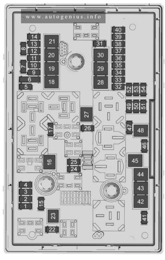
Assignment of the fuses in the engine compartment
| Fuses | Usage |
| 1 | Engine control module |
| 2 | O2 sensor |
| 3 | Fuel injection/ Ignition system |
| 4 | Fuel injection/ Ignition system |
| 5 | — |
| 6 | Heated mirrors |
| 7 | Fan control |
| 8 | O2 sensor/ Powertrain cooling |
| 9 | Rear window sensor |
| 10 | Vehicle battery sensor |
| 11 | Trunk release |
| 12 | Adaptive headlamps/ Automatic headlamp leveling |
| 13 | ABS valves |
| 14 | — |
| 15 | Engine control module |
| 16 | Starter |
| 17 | Transmission control module |
| 18 | Rear window defogger |
| 19 | Front power window |
| 20 | Rear power window |
| 21 | Rear electrical center |
| 22 | — |
| 23 | — |
| 24 | Right high-beam headlamp |
| 25 | Left high-beam headlamp |
| 26 | Front fog lamps |
| 27 | — |
| 28 | — |
| 29 | Electric parking brake |
| 30 | ABS pump |
| 31 | — |
| 32 | Airbag |
| 33 | Adaptive forward lighting/Automatic headlamp leveling |
| 34 | Exhaust gas recirculation |
| 35 | Power windows/Rain sensor/Exterior mirror |
| 36 | Climate control |
| 37 | — |
| 38 | Vacuum pump |
| 39 | Fuel system control module |
| 40 | Front windshield washer |
| 41 | — |
| 42 | Engine cooling fan |
| 43 | Windshield wipers |
| 44 | — |
| 45 | Engine cooling fan |
| 46 | — |
| 47 | Horn |
| 48 | Engine cooling fan |
| 49 | Fuel pump |
| 50 | Headlamp leveling/ Adaptive forward lighting |
| 51 | — |
| 52 | — |
| 53 | Transmission control module/Engine control module |
| 54 | Vacuum pump/ Instrument panel cluster/HVAC |
Passenger compartment
Fuse box location
The instrument panel fuse block is on the driver side of the instrument panel.
Fuse box diagram
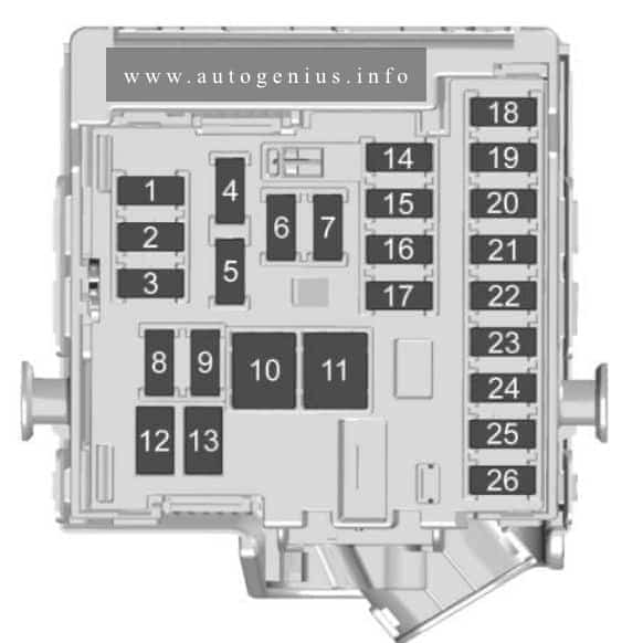
Assignment of the fuses in the passenger compartment
| Fuses | Usage |
| 1 | Displays |
| 2 | Body control module/Exterior lamps |
| 3 | Body control module/Exterior lamps |
| 4 | Infotainment system |
| 5 | Infotainment system/ Instrument |
| 6 | Power outlet |
| 7 | Power outlet |
| 8 | Body control module/Left low-beam headlamp |
| 9 | Body control module/Right low-beam headlamp |
| 10 | Body control module/Door locks |
| 11 | Interior fan |
| 12 | Driver power seat |
| 13 | Passenger power seat |
| 14 | Diagnostic connector |
| 15 | Airbag |
| 16 | Trunk lid relay |
| 17 | A/C system |
| 18 | Service diagnose |
| 19 | Body control module/Brake lamps/Reverse lamps/Interior lamps |
| 20 | — |
| 21 | Instrument panel |
| 22 | Ignition |
| 23 | Body control module |
| 24 | Body control module |
| 25 | — |
| 26 | Trunk power outlet accessory |
Rear Compartment
Fuse box location
The rear compartment fuse block, if equipped, is on the left side of the trunk behind a cover.
Fuse box diagram
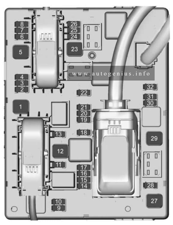
Assignment of the fuses in the rear compartment
| Fuses | Usage |
| 1 | Convertible control module/Right power rail |
| 2 | — |
| 3 | Rear parking assist |
| 4 | Selective catalytic reduction system |
| 5 | — |
| 6 | — |
| 7 | Power seats |
| 8 | Convertible control module |
| 9 | Selective catalytic reduction system |
| 10 | Selective catalytic reduction system |
| 11 | Tire pressure monitor/Rear vision camera |
| 12 | Convertible control module/Reverse lamps |
| 13 | — |
| 14 | Rear seat electrical folding |
| 15 | — |
| 16 | Rear vision camera/ Convertible control module |
| 17 | — |
| 18 | — |
| 19 | Heated steering whee |
| 20 | — |
| 21 | Heated seats |
| 22 | — |
| 23 | Convertible control module/Left power rail |
| 24 | Selective catalytic reduction system |
| 25 | — |
| 26 | Non-logistic mode |
| 27 | Passive entry/ Passive start |
| 28 | — |
| 29 | Hydraulic unit |
| 30 | — |
| 31 | — |
| 32 | — |
WARNING: Terminal and harness assignments for individual connectors will vary depending on vehicle equipment level, model, and market.