Cadillac Fleetwood (1995) – fuse box diagram
Year of production: 1995
Instrument panel fuse block
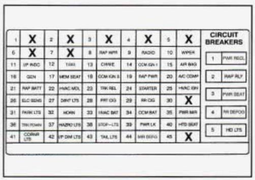
| Fuse | Usage |
| RAP WPR | Component Center (RAP Wiper) Relay |
| RADIO | Radio Receiver |
| WIPER | Windshield Wipermasher Switch |
| I/P INDC | Inflatable Restraint Diagnostic Energy Reserve (with Sensor) Module, Instrument Panel Cluste |
| TISIG | Parmeutral Position and Backup Lamp Switch, Turn Signal Lamp Flasher |
| CHIME | Warnin Alarm Cruise Control Release Switch, Inside Rearview Mirror,%ear dindow Defogge! Relay, Parmeutral Position and Backup Lamp Switch, Automatic Level Control Sensor |
| CCM IGN 1 | Central Control Module (CCM) |
| AIR BAG | Inflatable Restraint Diagnostic Energy Reserve (with Sensor) Module |
| GEN | Generator, Secondary Engine Cooling Fan Relay |
| MEM SEAT | Driver’s Seat Ad’uster Memory Module, Heated Driver’s Seat Switch, Heated 4 assenger’s Seat Swltch |
| CCM IGN 3 | Central Control Module (CCM) Remote Control Door Lock Receiver and Theft Deterrent dodule, Cruise Control Module, Cruise Control Swtcht |
| RAP PWR | Accessory Time Delay Cut-Off (RAP Power) Relay |
| A/C COMP | A/C Compressor Relay, Primary Engine Cooling Fan Relay |
| RAP BATT | Component Center (RAP Wiper) Relay |
| HVAC MDL | Blower Motor Control Module |
| TRK REL | Rear Compartment Lid Release Switch |
| STARTER | Theft Deterrent Relay, Inflatable Restraint Diagnostic Energy Reserve (with Sensor) Module |
| HVAC IGN | Instrument Cluster, Heater-A/C Control, Vacum/Electric Solenoid, Electric Actuator |
| ELC SENS | Automatic Level Control Sensor, Rear Compartment Courtesy Lamp |
| D/INT LTS | Compartment Center Relay |
| FRT CIG | Front Cigar Lighter |
| RR CIG | Rear Cigar Lighter |
| PARK LTS | Park Lamp Relay |
| HORN | Horn Relay |
| HVAC BAT | Warning Alarm, Heater-A/C Control, Instrument Cluster, Headlamp Switch, Radio Reciver |
| CCM BAT | Center Control Module (CCM) |
| PWR MIR | Door Lock Switches, Outside Rearview Mirrors, Ignition Key Disable Relay Assembly |
| TRK PDWN | Rear Compartment Lid Pull-Down Actutor |
| HAZARD LTS | Hazard Lamp Flasher |
| STOP-LTS | Stoplamps Switch |
| PWR LK | Door Lock Relay |
| HTD SEAT | Heated Driver’s and Passenger’s Seat Control Modules |
| CORNR LTS | Instrument Cluster, Radio Control, Cornering Lamps, Turn Signal Switch, Front Park Lamps |
| I/P DIM LTS | Headlamp Switch Control for Interior Lamps, Dimming |
| TAIL LTS | Rear Taillamps, Rear Side Marker Lamps, License Lamp |
| MIR DEFG | Outside Rearview Mirror Defogger |
| Circuit Breaker | Usage |
| PWR RECL | Lumbar, Power Antenna |
| RAP RLY | Accesory, Time Delay Cut-Off (RAP Power) Relay |
| PWR SEAT | Driver’s amd Passenger’s Adjuster Switches, Driver’s Seat Adjuster Memory Module, Driver’s and Passenger’s Seats Recline Switches |
| RR DEFOG | Rear Defogger Relay |
| HD LTS | Headlamp Relay, Daytime Running Lamps (DRL) Relay |
Underhood Electrical Center
The electrical center is located on the passenger side wheel housing in the engine compartment.
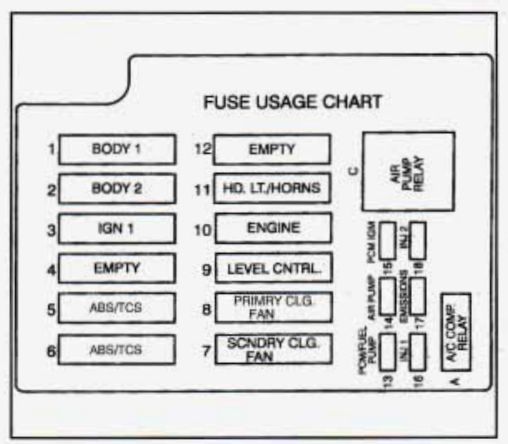
| Maxi Fuse | Usage |
| BODY 1 | Circuit Breakers: PWR SEAT, RRDEFOG; I/P Fuses: TRK PDWN, WRD LTS, HTD SEAT, STOP-LTS, PWR LK |
| BODY 2 | Circuit Breaker: RAP RLY, I/P Fuses: RAP BAm, HVAC MDL, ELC SENS, D/INT LTS, FRT CIG, RRCIG, HVAC BAT, CCM BAT, PWR MIR |
| IGN 1 | Concealed Fuse; I/p Fuses: RAP WPR, RADIO, WIPER, I/P INDC, T/SIG, CHIME, .CCM IGN 1, AIR BAG, STARTER; U/H Electrical Center: PCM IGN, INJ1, EMISSIONS, I |
| ABSECS (#5) | ABS/TCS Brake Pressure.Modulator Valve |
| ABSECS (#6) | ABS/TCS Brake Pressure.Modulator Valve |
| SCNDRY CLG FAN | Secondary Engine Cooling Fan Rel |
| PRIMRY CLG FAN | Pfimary .Engine Cooling Fan Relay |
| LEVEL CONTROL | Automatic Level Control Air Compress |
| ENGINE | U/H Electrical Center: PCM/FUEL PUMP, AIR PUMP |
| HEADLIGHTS/ HORNS |
Circuit-Breaker: HD LTS; I/P Fuses: PARK LTS, HORN |
| Mini Fuse | Usage |
| PCM/FUEL PUMP | Fuel Pump Relay, Fuel Pump/Engine Oil Pressure Indicator Switch, Powertrain Control Module (PCM) |
| AIR PUMP | Seconday Air’Injection (AIR) Pump Relay |
| PCM/IGN | Powertrain Control Module (PCM), Ignition Coil |
| INJ 1 | Fuel Injectors Cylinders 1,4,6,7 |
| EMISSIONS | Exhaust Gas.Recirculation (EGR); Vacuum Control Signal Solenoid Valve, Secondary Air Injection (AIR), Pump Relay (Coil), Mass-&Flow Sensor, Electronic Transmission, Left and Right Heated Oxygen Sensors, Evaporative Emission (EVAP)l Canisterpurge Solenoid Valve |
| INJ 2 | Fuel Injectors Cylinders 2,3,5, 8 |
| Relay | Usage |
| A/C COMP RELAY | A/C Compressor Relay |
| AIR PUMP RELAY | Secondary Air Injection -(AIR) Pump Relay |
WARNING: Terminal and harness assignments for individual connectors will vary depending on vehicle equipment level, model, and market.