
Dodge Caliber (2007 – 2012) – fuse box diagram
Year of production: 2007, 2008, 2009, 2010, 2011, 2012
Fuse box diagram
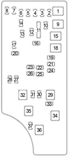
| No. |
A |
Protected Component |
| 1 | – | – |
| 2 | 20 | All Wheel Drive Control Module (4WD/AWD) |
| 3 | 10 | Stop Lamp Switch |
| 4 | 10 | Ignition Switch, Sentry Key Remote Entry Module, Engine Control Module, Totally Integrated Power Module (TIPM) |
| 5 | – | – |
| 6 | 10 | Occupant Classification Module, Left Vanity Lamp, Hands Free Module, Satellite Receiver, Mirror Switch |
| 7 | 30 | Fuse: “14”, “20”, “21” |
| 8 | 30 | Fuse: “6”, “17”, “19” |
| 9 | – | – |
| 10 | 20 | Cluster |
| 11 | – | – |
| 12 | 20 | Inverter Module |
| 13 | 20 | Dome Lamp |
| 14 | 10 | Cluster |
| 15 | 50 | Radiator Fan (Low/High) Relay, Radiator Fan (Medium/High) Relay |
| 16 | 15 | Power Outlet (Instrument Panel), Power Outlet (AC), Sunroof, Rear Wiper |
| 17 | 10 | Transmission Control Module (CVT), Steering Control Module, Sentry Key Remote Entry Module |
| 18 | 40 | Main Relay (Fuse: “23”, “26”, “32”) |
| 19 | 20 | Radio Amplifier, Subwoofer |
| 20 | 15 | Radio |
| 21 | 10 | Export: Intrusion Transceiver Module, Siren |
| 22 | 10 | A/C Heater Control, Compass |
| 23 | 15 | Gasoline: Ignition Coils, Ignition Capacitor |
| 15 | Diesel: Glow Plug Module, Valve Block Assembly, Mass Air Flow Sensor | |
| 24 | 25 | Sunroof Motor |
| 25 | 10 | Heated Mirror |
| 26 | 15 | Gasoline: Fuel Injectors, Camshaft Position Solenoid |
| 15 | Diesel: A/C Compressor Solenoid, EGR Air Flow Control Valve | |
| 27 | 10 | Occupant Restraint Controller Module (ORC) |
| 28 | 10 | Occupant Restraint Controller Module (ORC) |
| 29 | – | – |
| 30 | 20 | Heated Seats Module |
| 31 | 10 | Diesel: Cabin Heater Relay No.1, Cabin Heater Relay No.2 |
| 32 | 30 | Gasoline: Powertrain Control Module |
| 30 | Diesel: Engine Control Module | |
| 33 | 10 | Data Link Connector, Powertrain Control Module (Gasoline), Bank Switch, Main Relay, Radiator Fan (Low/High) Relay, Radiator Fan (Medium/High) Relay, Radiator Fan (Series/Parallel) Relay |
| 34 | 30 | ABS |
| 35 | 40 | ABS |
| 36 | – | – |
| 37 | – | – |
| No. |
A |
Protected Component |
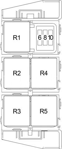
| 6 | 25 | Diesel: Cabin Heater Relay No.2 |
| 8 | 25 | Diesel: Cabin Heater Relay No.1 |
| 10 | 50 | Diesel: Glow Plug Module |
| Relay | ||
| R1 | Radiator Fan (Low/High) | |
| R2 | Radiator Fan (Series/Parallel) | |
| R3 | Radiator Fan (Medium/High) | |
| R4 | Main | |
| R5 | – | |
WARNING: Terminal and harness assignments for individual connectors will vary depending on vehicle equipment level, model, and market.