Ford Thunderbird (1980 – 1982) – fuse box diagram
Year of production: 1980, 1981, 1982
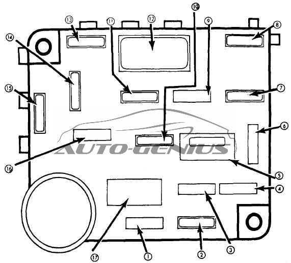
Fuse box diagram
| № |
A |
Protected Component |
| 1 | 5 | Instrument lights and interior light |
| 2 | 10 | Throttle solenoid, seat belt warning buzzer |
| 3 | — | — |
| 4 | 20 | Horn and cigar lighter |
| 5 | 20 | Circuit Breaker: Power seats and door locks |
| 6 | 20 | Choke heater |
| 7 | 15 | Courtesy lights, clock feed, key warning buzzer, headlight warning buzzer, seat back latch relay and illuminated entry |
| 8 | 15 | Standard: Parking, tail and license lights |
| 10 | Console: Parking, tail and license lights | |
| 9 | — | — |
| 10 | 20 | Radio, power antenna and CB radio |
| 11 | 20 | Accessories, air conditioning clutch, heated rear window relay coil, deck lid release, speed control and illuminated entry |
| 12 | 6 | Circuit Breaker Windshield wipers and wiper/washers |
| 13 | 15 | Stop and hazard warning lights |
| 14 | 15 | Turn signal and back-up lights |
| 15 | 30 | Air conditioning and automatic temperature control blower |
| 16 | — | — |
| 17 | 20 | Power windows |
Circuit Breaker:
Fusible Links:
In-Line Fuse:
|
||
WARNING: Terminal and harness assignments for individual connectors will vary depending on vehicle equipment level, model, and market.