Hyundai Elantra (2019) – fuse box diagram
Year of production: 2019
Instrument panel
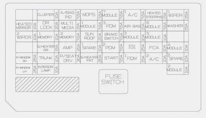
| Fuse name | [A] | Protected component |
| HEATED MIRROR | 10 | Driver/Passenger Power Outside Mirror, A/C Control Module |
| WIPER 2 | 10 | PCM, BCM |
| P/WINDOW RH | 25 | Power Window RH Relay |
| P/WINDOW LH | 25 | Power Window LH Relay, Driver Safety Power Window Module |
| CLUSTER | 10 | CLUSTER |
| DR LOCK | 20 | Door Lock/Unlock Relay, E/R Junction Block (Two Turn Unlock Relay) |
| MEMORY 1 | 10 | Driver/Passenger Door Module, Driver IMS Module, A/C Control Module, Instrument Cluster, Electro Chromic Mirror, Data Link Connector, Blind Spot Detection Radar LH/RH, Digital Clock |
| S/HEATER RR | 15 | Rear Seat Warmer Control Module |
| TRUNK | 10 | Trunk Relay |
| INTERIOR LAMP | 10 | Room Lamp, Front Vanity Lamp LH/RH, Overhead Console Lamp, Ignition Key ILL. & Door Warning Switch, Trunk Room Lamp |
| A/BAG IND | 7,5 | Instrument Cluster, A/C Control Module |
| MULTI MEDIA | 15 | CD Player, Audio, A/V & Navigation Head Unit |
| MEMORY 2 | 7,5 | — |
| AMP | 25 | AMP |
| P/SEAT DRV | 30 | Driver Seat Manual Switch, Driver IMS Module |
| MDPS | 7,5 | MDPS Unit |
| MODULE 1 | 7,5 | Key Interlock, Driver/Passenger Smart Key Outside Handle, Driver/Passenger Door Module, BCM, Driver/Passenger Outside Mirror Switch/Motor |
| SUNROOF | 20 | Sunroof Moto |
| SPARE 1 | 10 | — |
| S/HEATER FRT | 20 | Front Seat Warmer Control Module |
| MODULE 7 | 7,5 | Front Seat Warmer Control Module, Rear Seat Warmer Control Module, Sunroof Motor, BCM |
| PDM 3 | 7,5 | Smart Key Control Module, Immobilizer Module |
| BRAKE SWITCH | 7,5 | Stop Lamp Switch, Smart Key Control Module |
| PDM 2 | 7,5 | Smart Key Control Module, Immobilizer Module |
| START | 7,5 | W/O Smart Key : Transmission Range Switch, Ignition Lock Switch With Smart Key :Transmission Range Switch, PCM |
| A/C | 7,5 | Ionizer, A/C Control Module, E/R Junction Block (A/Con Relay, Blower Relay), Gasoline PTC Relay |
| AIR BAG | 15 | SRS Control Module, Passenger Occupant Detection Sensor |
| MODULE 3 | 10 | Stop Lamp Switch, BCM, Sport Mode Switch, Driver/Passenger Door Module |
| IG1 | 25 | PCB Block (Fuse : ABS3, ECU5, TCU2) |
| PDM 1 | 15 | Smart Key Control Module |
| HEATED STEERING | 15 | BCM |
| MODULE 6 | 7,5 | BCM, Smart Key Control Module |
| MODULE 5 | 10 | Crash Pad Switch, Electro Chromic Mirror, A/T Shift Lever Indicator, A/V & Navigation Head Unit, Audio, A/C Control Module, Console Switch LH/RH, Head Lamp Leveling Device LH/RH, Front Seat Warmer Control Module, Rear Seat Warmer Control Module, Driver IMS Module |
| FCA | 10 | FCA Module |
| A/CON 2 | 10 | E/R Junction Block (Blower Relay), Blower Motor, Blower Resistor, A/C Control Module |
| WIPER 1 | 25 | Wiper Motor, PCB Block (Front Wiper (Low) Relay |
| WASHER | 15 | Multifunction Switch |
| MODULE 4 | 10 | Lane keeping Assist System, Parking Assist Buzzer, BCM |
| SPARE 2 | 10 | — |
| MODULE 2 | 10 | E/R Junction Block (Power Outlet Relay), USB Charging Connector, Smart Key Control Module, BCM, Audio, A/V & Navigation Head Unit, CD Player, Power Outside Mirror Switch, AMP, Driver Door Module, Digital Clock, Console Switch |
Engine compartment
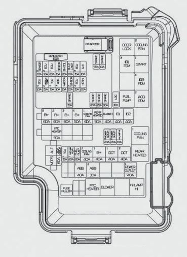
| Fuse name | [A] | Protected component | |
| MULTI FUSE-1 | MAIN | 180 | Fuse : ABS1, ABS2, POWER OUTLET |
| MDPS | 80 | MDPS Unit | |
| MULTI FUSE-2 | B+5 | 60 | PCB Block (Fuse : ECU3, ECU4, HORN, A/C COMP, ENGINE CONTROL RELAY) |
| B+2 | 60 | Smart Junction Block (Fuse : S/HEATER FRT, ARISU | |
| B+3 | 60 | Smart Junction Block (Fuse : ARISU, IPS) | |
| B+4 | 50 | Smart Junction Block (Fuse : S/HEATER RR, P/WINDOW LH, P/WINDOW RH, TRUNK, SUNROOF, AMP, P/SEAT DRV) | |
| COOLING FAN 1 | 60 | — | |
| REAR HEATED | 50 | Rear Heated Relay | |
| BLOWER | 40 | Blower Relay | |
| IG1 | 40 | Ignition Switch, E/R Junction Block (PDM #2, #3 (ACC/IG1) Relay) | |
| IG2 | 40 | Ignition Switch, E/R Junction Block (PDM #4 (IG2) Relay, START Relay) | |
| FUSE | B/UP LAMP | 10 | Electro Chromic Mirror, Rear Combination Lamp (IN) LH/RH, Smart Junction Block (IPS Control Module) |
| POWER OUTLET 3 | 20 | Cigarette Lighter | |
| POWER OUTLET 2 | 20 | Front Power Outlet | |
| H/LAMP HI | 10 | BI-FUNC H/LP RLY (coil) | |
| TCU 1 | 15 | — | |
| VACUUM PUMP 1 | 20 | — | |
| A/CON | 10 | A/Con Relay | |
| COOLING FAN 2 | 40 | Cooling Fan 1/2 Relay | |
| B+1 | 40 | Smart Junction Block (Leak Current Autocut Device, Fuse : BRAKE SWITCH, MODULE 1, DR LOCK, PDM 1, PDM 2) | |
| DCT1 | 40 | — | |
| DCT2 | 40 | — | |
| S/FUEL PUPMP | 15 | — | |
| ABS1 | 40 | ESC Module, Multipurpose Check Connector | |
| ABS2 | 30 | ESC Module, Multipurpose Check Connector | |
| POWER OUTLET 1 | 40 | Power Outlet Relay | |
| Fuse name | [A] | Protected component |
| ECU 5 | 10 | PCM |
| VACUUM PUMP | 15 | — |
| SPARE | 20 | — |
| ABS 3 | 10 | ESC Module, Multipurpose Check Connector |
| TCU 2 | 15 | Transmission Range Switch, E/R Junction Block (Fuse : B/UP LAMP |
| ECU 4 | 15 | PCM |
| ECU 3 | 15 | PCM |
| FUEL PUMP | 20 | Fuel Pump Relay |
| SENAOR 2 | 10 | Canister Close Valve, Purge Control Solenoid Valve, Variable Intake Solenoid Valve, E/R Junction Block (Cooling Fan 1/2 Relay) |
| ECU2 | 10 | — |
| ECU1 | 20 | PCM |
| INJECTOR | 15 | Injector #1/#2/#3/#4 |
| SENSOR 1 | 15 | Oxygen Sensor (UP/DOWN) |
| IGN COIL | 20 | Ignition Coil #1/#2/#3/#4 |
| SENSOR 3 | 10 | Fuel Pump Relay |
| HORN | 20 | Horn Relay |
WARNING: Terminal and harness assignments for individual connectors will vary depending on vehicle equipment level, model, and market.