Hyundai Elantra GT (2016 – 2017) – fuse box diagram
Year of production: 2016, 2017
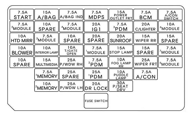
Instrument panel
| Description | Fuse rating | Protected component |
|---|---|---|
| C/LIGHTER | 20A | Console Cigar Light, Rear Power Outlet |
| 1 MODULE | 7.5A | Sport Mode Switch |
| 4 MODULE | 7.5A | A/ C Control Module, Head Lamp Leveling Device Actuator LH/RH, Fuel Filter Warning Sensor(D4FD), Rear Parking Assist System |
| 3 MODULE | 7.5A | Instrument Cluster, BCM, Tire Pressure Monitoring Module, Audio, Driver/Passenger Seat Warmer Module, ATM shift lever Ind |
| POWER OUTLET FRT | 15A | Front Power Outlet |
| HTD MIRR | 10A | Driver/Passenger Power Outside Mirror, A/C Control Module, ECU |
| WIPER FRT | 25A | ICM Relay Box (Rain Sensor Relay), Multifunction Switch, E/R Fuse & Relay Box (RLY. 7) Front Wiper Motor |
| A/CON | 7.5A | A/C Control Module, E/R Fuse & Relay Box (RLY. 4) |
| P/WDW LH | 25A | P/WDW LH Relay, Driver Safety Power Window Module (LHD) |
| T/GATE OPEN | 10A | Tail Gate, Rear Camera Open Actuator |
| P/SEAT DRV | 30A | Driver Manual Switch |
| 2 MODULE | 7.5A | ICM Relay Box, Rear Camera Module, Electro Chromic Mirror |
| WIPER RR | 15A | Rear Wiper Relay, Rear Wiper Motor, Multifunction Switch |
| STOP LAMP | 15A | Stop Lamp Switch |
| P/WDW RH | 25A | P/WDW RH Relay, Driver Safety Power Window Module (RHD) |
| 2 PDM | 7.5A | Smart Key Control Module, Start/Stop Button Switch, Ultrasonic Instruction Protection Sensor |
| 5 MODULE | 7.5A | EMS BOX (Head Lamp Washer Relay), Ionizer Unit, Panorama Sunroof, DSL BOX (PTC Relay), E/R Fuse & Relay BOX(RLY.), Driver/Passenger Seat Warmer Module |
| IG1 | 20A | E/R Fuse & Relay Box (Fuse – F) |
| 6 MODULE | 10A | Outside Mirror Switch, Audio, Navigation Head Unit, Digital Clock |
| MDPS | 7.5A | EPS Control Module |
| DR LOCK | 20A | Door Lock/Unlock Relay, ICM Relay BOX (Dead Lock Relay), Driver/Passenger Door Lock Actuator, Fuel filler actuator, Door Lock Actuator LH/RH |
| INTERIOR LAMP | 10A | Vanity Lamp LH/RH, Overhead Console Lamp, Room Lamp, Luggage Lamp, DR Warning Switch |
| MULTI MEDIA | 15A | Audio, Navigation Head Unit |
| A/BAG | 15A | SRS Control Module |
| 1 MEMORY | 7.5A | Instrument Cluster |
| A/BAG IND | 7.5A | Instrument Cluster |
| 3 PDM | 7.5A | Smart Key Control Module, Ultrasonic instrusion Protection Sensor |
| 2 MEMORY | 10A | Outside Mirror Switch, Tire Pressure Monitoring Module, BCM, Auto Light & Photo Sensor, OBD, Digital Clock, A/C Control Module |
| 1 PDM | 25A | Smart Key Control Module |
| START | 7.5A | W/O Button Start: E/R Fuse & Relay Box (RLY.) Ignition Lock Switch, Transaxle Range Switch With Button Start: ECM/PCM, Transaxle Range Switch |
| SUNROOF | 20A | Panorama Sunroof |
| BCM | 7.5A | BCM, Smart Key Control Module |
| A/CON SWITCH | 7.5A | A/C Control Module |
| 7 MODULE | 7.5A | BCM, Smart Key Control Module |
| FOG LAMP RR | 10A | Rear Fog Lamp |
| PUDDLE LAMP | 10A | Driver/Passenger Power Outside Mirror |
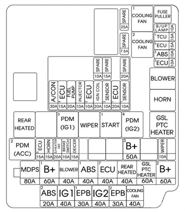
Engine compartment fuse panel
| Description | Fuse rating | Protected component |
|---|---|---|
| MULTI FUSE | ||
| MDPS | 80A | EPS Control Module |
| 1B+ | 60A | I/P Junction Box (IPS 0 (4CH), IPS 1 (4CH), IPS 2 (2CH), Fuse – F13/F14/F19/F20/F21 /F26/ F36) |
| 1 ABS | 40A | ESC Control Module, Multipurpose Check Connector |
| BLOWER | 40A | RLY. 4 (Blower Relay) |
| 2B+ | 60A | I/P Junction Box (IPS 3 (4CH), IPS 4 (4CH), Fuse – F2/F7/F9/F15) |
| GSLPTC HEATER | 60A | RLY. 12 (GASOLINE PTC Relay) |
| FUSE | ||
| COOLING FAN | 40A | RLY 1 (C/FAN LO Relay), RLY 2 (C/FAN HI Relay) |
| 2 ABS | 20A | ESC Control Module, Multipurpose Check Connector |
| IG2 | 40A | RLY 9 (Start Relay), Ignition Switch (W/O Button Start), RLY 6 (PDM 4 (IG2) Relay, With Button Start) |
| IG1 | 40A | W/O Button Start: Ignition Switch, With Button Start: RLY 8 (PDM 2 (ACC) Relay)/RLY. 10 (PDM 3 (IG1) Relay |
| DEICER | 15A | ICM Relay Box (Front Deicer Relay) |
| 3B+ | 50A | I/P Junction Box (Leak Current Autocut Device, Fuse – F18/F25/F30/F34/F38) |
| BRAKE SWITCH | 10A | Smart Key Control Module, Stop Signal Relay |
| S/HEATER FRT | 20A | Driver/Passenger Seat Warmer Module |
| WIPER | 10A | PCM/ECM |
| HORN | 15A | RLY. 5 (Horn Relay), ICM Relay Box (B/A Horn Relay) |
| 1 TCU | 15A | A/T – TCM (D4FD), Transaxle Range Switch |
| 6 ECU | 15A | RLY. 9 (D4FD, Start Relay), ECM/PCM |
| 3 ABS | 10A | ESC Control Module, Multipurpose Check Connector |
| 3 ECU | 10A | ECM/PCM, Air Flow Sensor, Stop Lamp Switch |
| B/UP LAMP | 10A | M/T – Back-Up Lamp Switch, A/T – Rear Combination Lamp (IN) LH/RH, Rear Curtain Module, Navigation Head Unit, Electro Chromic Mirror, IPS Control Module |
| 1 ECU | 20A | G4FD/D4FD : ECM G4NA/G4NC : PCM (A IT), ECM (M/T) |
| IGN COIL | 20A | G4NA : Ignition Coil #1/#2/#3/#4, Condenser |
| 2 SENSOR | 10A | G4FD : Oxygen Sensor (UP/DOWN), Variable Intake Solenoid Valve, Purge Control Solenoid Valve G4NA/G4NC : Oxygen Sensor (UP/DOWN), Variable Intake Solenoid Valve, Purge Control Solenoid Valve D4FD : Camshaft Position Sensor, EGR Cooling Bypass Solenoid Valve, Diesel Box (Glow Relay) |
| 1 SENSOR | 10A | G4FD : Oil Control Valve #1/ #2, Oil Level Sensor, E/R Fuse & Relay Box (RLY. 1) G4NA/G4NC : Oil Control Valve #1/ #2, Camshaft Position Sensor (Intake/Exhaust), E/R Fuse & Relay Box (RLY. 1) D4FD : E/R Fuse & Relay Box (RLY 1), Diesel Box (PTC Heater Relay#1), Lambda Sensor, VGT Control Solenoid Valve |
| 2 ECU | 10A | G4FD : ECM G4NA : Fuel Pump Relay G4NC : Fuel Pump Relay, PCM (A/T), ECM (M/T) D4FD : Oil Level Sensor, Fuel Pressure Regulating Valve |
| INJECTOR | 10A | G4NA – Injector #1/#2/#3/#4 |
| 4 ECU | 15A | G4NA/G4NC : PCM (ATT), ECM (M/T) |
| FUEL PUMP | 20A | EMS Box (Fuel Pump Relay) |
| A/CON | 30A | EMS Box (Air Conditioner) |
| EMS | 40A | EMS Box |
Assignment of the relay
| Description | Protected component | Type |
|---|---|---|
| 1 COOLING FAN | C/FAN LO RELAY | PLUG MICRO |
| 2 COOLING FAN | C/FAN HI RELAY | PLUG MICRO |
| BLOWER | BLOWER RELAY | PLUG MICRO |
| HORN | HORN RELAY | PLUG MICRO |
| 4 PDM (IG2) | PDM 4 (IG2) RELAY | PLUG MICRO |
| WIPER | FRONT WIPER RELAY | PLUG MICRO |
| 1 PDM (ACC) | PDM 1 (ACC) RELAY | PLUG MICRO |
| START 1 | START RELAY | PLUG MICRO |
| 3 PDM (IG1) | PDM 3 (IG1) RELAY | PLUG MICRO |
| REAR HEATED | RR HTD RELAY | PLUG MICRO |
| GSL PTC HEATER | PTC Heater/Fuel Filter | PLUG MINI |
WARNING: Terminal and harness assignments for individual connectors will vary depending on vehicle equipment level, model, and market.