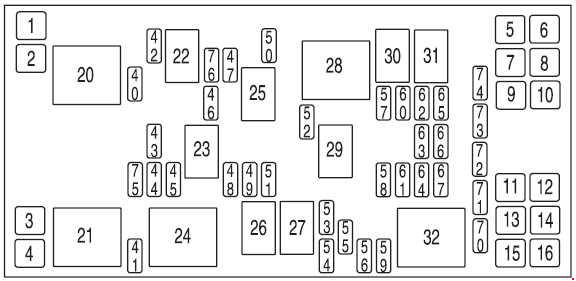
| No. |
A |
Protected components |
| 1 |
— |
Not used |
| 2 |
30 |
Right cooling fan |
| 3 |
30 |
Left cooling fan |
| 4 |
30 |
Starter solenoid |
| 5 |
30 |
Right-hand power sliding door |
| 6 |
30 |
SJB accessory #2 (driver power window) |
| 7 |
30 |
Auxiliary blower motor |
| 8 |
40 |
Anti-lock Brake System (ABS) #2 (coil power) |
| 9 |
30 |
Power liftgate |
| 10 |
30 |
SJB accessory #1 (passenger window, radio, vent windows) |
| 11 |
30 |
Left power seat/heated seat |
| 12 |
40 |
ABS #1 (pump motor) |
| 13 |
40 |
Rear defroster |
| 14 |
30 |
Front climate control system blower motor |
| 15 |
30 |
Right power seat/heated seat |
| 16 |
30 |
Left-hand power sliding door |
| 40 |
15 |
Engine #1 (A/C relay coil, IMRC, HEGO sensors, Canister purge, Transmission module, Canister vent (’04-’05)) |
| 41 |
25 |
Horn |
| 42 |
10 |
A/C clutch |
| 43 |
15 |
Engine #2 (Cooling fan relays, Injectors, PCM, MAF sensor, IAC, Ignition coil, ESM) |
| 44 |
10 |
Heated PCV |
| 45 |
15 |
High beams |
| 46 |
20 |
Trailer stop/turn lamps |
| 47 |
15 |
Fuel pump, Fuel pump shut-off switch |
| 48 |
15 |
Fog lamps |
| 49 |
10 |
PCM KAP, Canister vent (’06-’07) |
| 50 |
10 |
Alternator |
| 51 |
10 |
Adjustable pedals (non-memory) or memory module |
| 52 |
20 |
Trailer tow park lamps |
| 53 |
10 |
Heated mirrors |
| 54 |
30 |
Front wiper motor |
| 55 |
25 |
Rear wiper motor |
| 56 |
30 |
Premium sound radio |
| 57 |
20 |
’04: Cigar lighter |
| 58 |
30 |
SJB #1 – Center High-Mounted Stop Lamp (CHMSL), License plate lamps, OBD II, Dome lamp, Auxiliary blend doors, Switch illumination (feeds F-8, F-9, F-10nd F-ll) |
| 59 |
20 |
Radio (non-premium) |
| 60 |
30 |
SJB #4 – Back-up lamps, Theft sounder (’04), Door locks |
| 61 |
20 |
’04: 3rd row power point |
| 62 |
30 |
SJB #3 – Right comering/auxiliary lamps, Right low beam, Left front park/turn lamps, Left rear park/stop/tum lamps, Instrument panel courtesy lamps, Step well lamps, Left signal mirror, Clock, Cluster, Message center (SJB F-15), Switch illumination for: overhead console, DVD/Rear climate control system, Headlamp switch illumination, Climate control illumination |
| 63 |
20 |
Instrument panel power point, Cigar lighter (’05-’07) |
| 64 |
20 |
Ignition switch #1 feed |
| 65 |
30 |
SJB #2 – Left cornering/auxiliary lamps, Left low beam, Right front park/turn lamps, Right rear park/stop/turn lamps, Puddle lamps, Mirror signals, Visors, 2nd and 3rd row lamps, Cargo lamp, Defroster indicator |
| 66 |
20 |
2nd row seat power point, 3rd row power point (’05-’07) |
| 67 |
20 |
Ignition switch #2 feed |
| 70 |
— |
Not used |
| 71 |
— |
Not used |
| 72 |
— |
Not used |
| 73 |
— |
Not used |
| 74 |
— |
Not used |
| Relay |
| 20 |
Powertrain Control Module (PCM) power |
| 21 |
Horn |
| 22 |
A/C clutch |
| 23 |
High beams |
| 24 |
Starter |
| 25 |
Fuel pump |
| 26 |
Fog lamps |
| 27 |
Not used |
| 28 |
Auxiliary blower |
| 29 |
Trailer park lamps |
| 30 |
Left trailer stop/turn lamps |
| 31 |
Right trailer stop/turn lamps |
| 32 |
Rear defroster |
| Diode |
| 75 |
PCM |
| 76 |
A/C clutch |