
Mitsubishi Eclipse (1995 – 1999) – fuse and relay box diagram
Year of production: 1995, 1996, 1997, 1998, 1999
This article focuses on the second-generation Mitsubishi Eclipse, manufactured between 1995 and 1999. It includes fuse box diagrams for the 1995, 1996, 1997, 1998, and 1999 models, details the locations of the fuse panels within the vehicle, and explains the function of each fuse (fuse layout).
Passenger compartment fuse box
Fuse Box Location
The fuses are located below the instrument panel.
Fuse Box Diagram
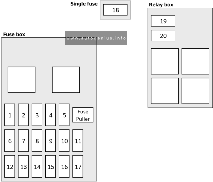
Assignment of the fuses in the passenger compartment
| № | Amps | Load circuit |
|---|---|---|
| 1 | 15A | Amplifier |
| 2 | – | – |
| 3 | 10A | Back-up lamp, combination meter (2.0 non turbo), EATX-ECM (2.0 non turbo) and SRS-ECU |
| 4 | 10A | Turn-signal and hazard frasher unit |
| 5 | 10A | Theft-alarm horn and theft-alarm horn relay |
| 6 | 30A | Defogger and defogger switch |
| 7 | – | – |
| 8 | 10A | Combination meter, ETACS-ECU, SRS-ECU, sunroof-ECU, immobilizer-ECU, motor antenna assembly and auto-cruise control main switch |
| 9 | 20A | Windshield intermittent wiper relay, windshield wiper motor, windshield washer motor, rear intermittent wiper relay, rear wiper motor, rear washer motor and headlamp washer relay |
| 10 | 10A | Door lock power relay, door lock actuator and diagnosis connector |
| 11 | 30A | Blower motor |
| 12 | – | – |
| 13 | 10A | DRL-ECU, DRL relay (1), power window relay, blower relay, A/C-ECU, radiator tan relay, condensor fan relay (HI), defogger relay and ABS-ECU |
| 14 | 15A | Cigarette lighter |
| 15 | 10A | Auto-cruise-ECU (2.0 turbo), combination meter (2.0 turbo) and ELC 4-speed automatic transaxle control module (2.0 turbo) |
| 16 | – | – |
| 17 | 20A | Sunroof-ECU |
| 18 | Auto-cruise control system | |
| 19 | 10A | Remote controlled mirror |
| 20 | – | – |
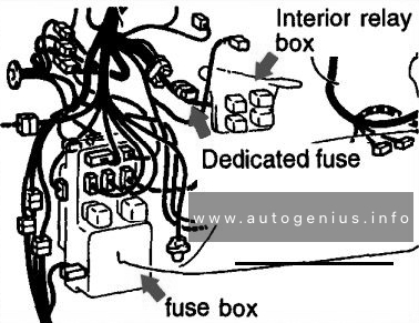
Engine compartment fuse box
Fuse Box Diagram
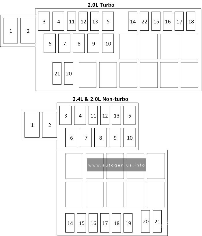
Assignment of the fuses in the engine compartment
| № | Amps | Circuit |
|---|---|---|
| 1 | 60A | Circuits using dedicated fuses №17 and 20 (engine compartment), circuit using multi-purpose fuses №1, 5, 6, 10, and 11 (instrument panel) |
| 2 | 100A/120A | Charging system, fusible links №1 and 4 (engine compartment). |
| 3 | 30A | Convertible top |
| 4 | 30A/40A | Power seat and power windows |
| 5 | 20A | MPI/MFI system, ELC 4-speed AT and immobilizer system |
| 6 | 40A | Charging system, fog lights, circuits using headlamp relay, and circuit using tail lamp relay |
| 7 | 30A | Fuse №17 (instrument panel) and ignition switch |
| 8 | 30A | Air conditioner and cooling system / Radiator fan |
| 9 | 50A | Anti-skid braking system (ABS) |
| 10 | – | – |
| 11 | 15A | Anti-lock braking system, auto-cruise control system and stop lamp |
| 12 | 15A | Horn |
| 13 | 15A | Turn-signal lamp and hazard lamp |
| 14 | 10A/15A | Tail lamp, position lamp and licence plate lamp (10A); Glove compartment light, license plate fight, lighting monitor buzzer, rheostat, side marker light, taillight and illumination light (15A) |
| 15 | 15A | Front fog lamp |
| 16 | 10A | Headlamp and headlamp leveling system / Hight-beam indicator light |
| 17 | 10A | Air conditioner |
| 18 | 20A | Air conditioner and cooling system |
| 19 | 10A | Air conditioner, auto-cruise control system, cigarette lighter, front fog lamp, glove box lamp, heater, headlamp leveling system, headlamp washer, lighting monitor buzzer, meter and gauge, radio with tape player, rear fog lamp, rear window defogger, rear wiper and washer, remote controlled mirror, tail lamp, position lamp, licence plate lamp, turn-signal lamp and hazard lamp |
| 20 | 10A | Anti-lock braking system, auto-cruise control system, central door locking system, door lamp, foot lamp, luggage compartment lamp, ignition key cylinder illumination lamp, immobilizer system, lighting monitor buzzer, meter and gauge, MPI system, radio with tape player, rear window, defogger and supplemental restraint system |
WARNING: Terminal and harness assignments for individual connectors will vary depending on vehicle equipment level, model, and market.