
Opel Movano (2010 – 2017) – fuse box diagram
Year of production: 2010, 2011, 2012, 2013, 2014, 2015, 2016, 2017
The Instrument Panel Fuse Panel
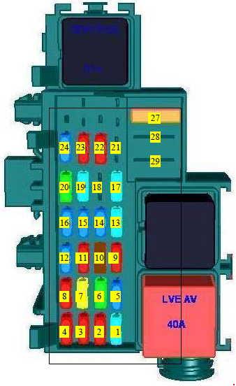
| Number | A | Description |
| 1 | 10 | Infotainment system, seat heating, (Relais servitude 1. Relais moteur tournant) |
| 2 | 10 | Power outlet 1 |
| 3 | 10 | Cigarette lighter |
| 4 | 10 | Power outlet 2 |
| 5 | 5 | Instrument panel |
| 6 | 30 | Central locking (UCE Habitacle (CPE, SUPCPE), BFR) |
| 7 | 25 | Turn signals, rear fog lights, body control module (UCE Habitacle + Batsecurite) |
| 8 | 5 | Diagnostic connector |
| 9 | — | — |
| 10 | 5 | ABS, Electronic Stability Program |
| 11 | 10 | Interior lights, brake lights |
| 12 | 5 | Body control module |
| 13 | 15 | Brake light |
| 14 | 5 | Body control module, power windows, air conditioning |
| 15 | 20 | Left heated rear window |
| 16 | 20 | Right heated rear window |
| 17 | 15 | Windscreen washer (Commandes sous volant) |
| 18 | 5 | Electronic immobiliser |
| 19 | 15 | Heated seats (BFRH2, ADPCNC, adaptation compiementaire) |
| 20 | — | — |
| 21 | 10 | Cornering lights |
| 22 | 10 | Infotainment system, seat heating, vehicle display screen, audio connections, alarm |
| 23 | 5 | Hands-free connection |
| 24 | 10 | Tachograph |
| 25 | — | – (emplacement diode) |
| 26 | — | – (emplacement diode) |
| 27 | 40 | Climate control fan |
| 28 | 10 | Additional adaptations (BFRH2, relais ACC deleste, relais servitude 1) |
| 29 | 40 | Power windows, body control module |
Fuse box in the engine compartment
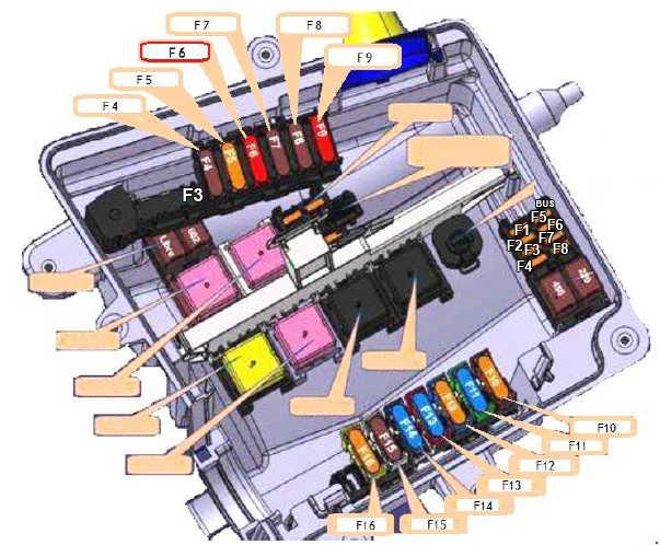
| Number | A | Description |
| F1 | — | — |
| F2 | — | — |
| F3 | 50 | BUS X62 |
| F4 | 40 | ABS ECU |
| F5 | 50 | Additional heating relay 1 |
| F6 | 50 | Purpose-built body conversion, X62 BUS |
| F7 | 70 | Additional heating relay 2 |
| F8 | 70 | Rear lights, passenger compartment fuse-relay box, diesel heater resistance |
| F9 | 70 | Passenger compartment relay and fuse box |
| F10 | 50 | Motor fan relay 3, motor fan relays (rating depending on vehicle spec.) |
| 40 | ||
| F11 | 40 | Motor fan speed Relay 1,Motor fan speed Relay 2 (rating depending on vehicle spec.) |
| 50 | ||
| 60 | ||
| F12 | 40 | Starter motor |
| F13 | 60 | Heating interface unit |
| F14 | 60 | Heating interface unit |
| F15 | 70 | Diesel glow plug relay unit |
| F16 | 40 | Gearbox electro pump unit relay |
| 50 | Fuse box 2 | |
| BUS FUSE PLATE (260BA) | ||
| F1 | 5 | Lighting control relay power supply (GRUAU) Front and rear lighting |
| F2 | 5 | Lighting control relay power supply (GRUAU) Individual lighting (X81) |
| F3 | 15 | Relay 1155 power supply (70A + load shed accessory relay) |
| F4 | 25 | Relay 1155 power supply (70A + BCM battery relay) |
| F5 | 10 | Power supply for multimedia display from GRUAU kits |
| F6 | 5 | Door sill electronic control unit power supply |
| F7 | — | — |
| F8 | — | — |
| Number | A | Description |
| F1 | 7,5 | Right side light |
| F2 | 7,5 | Left side light |
| F3 | 10 | Right dipped beam lights |
| F4 | 10 | Left dipped beam lights |
| F5 | 20 | Fog lamps |
| F6 | 10 | Left main beam light |
| F7 | 10 | Right main beam light |
| F8 | 25 | ABS power supply |
| F9 | 30 | Windscreen wiper |
| F10 | 10 | Airbag PIS (primary ignition supply) |
| F11 | — | — |
| F12 | 20 | Gearbox ECU power supply (Front wheel drive) |
| F13 | — | — |
| F14 | — | — |
| F15 | — | — |
| F16 | 5 | Gearbox PIS (primary ignition supply) |
| F17 | 7,5 | Passenger compartment PIS (primary ignition supply) |
| F18 | 5 | Injection ECU/diesel heater relay |
| F19 | 10 | Rear running lights PIS (primary ignition supply) |
| F20 | — | — |
| F21 | — | — |
| F22 | 10 | Air conditioning (compressor) I |
| F23 | 5 | Defrosting (relay control) |
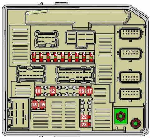
The optional fuse box
Located on the right-hand side (left- and right-hand drive). It is attached to the right-hand flange of the dashboard beam.
| Number | A | Description |
| 1 | 20 | Sliding door |
| 2 | 20 | Boot lid |
| 3 | 20 | Bus heated seat |
| 4 | 20 | Bus ESP |
| 5 | 40 | A/C info |
| 6 | 70 | BCM + battery feed |
| 7 | 70 | + load shed accessory feed |
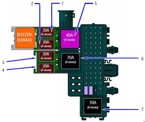
The relay box for the KPD option is located in the right-hand side of the dashboard.
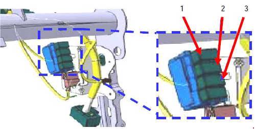
| Number | A | Description |
| 1 | 20 | + 12 V load shed current distribution power supply |
| 2 | 20 | Engine running information |
| 3 | 20 | Heated seat |
WARNING: Terminal and harness assignments for individual connectors will vary depending on vehicle equipment level, model, and market.