Toyota Aygo (AB10; 2005 – 2011) – fuse box diagram
Year of production: 2005, 2006, 2007, 2008, 2009, 2010, 2011
Fuse box in engine compartment (top side)
Fuse box in engine compartment (back side)
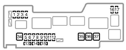
Fuse box in instrument panel (left side)

Fuse box in instrument panel (right side)
Fuse box in instrument panel (back side)

Fuses (type A)
| Fuse | Ampere rating [A] | Description | |
| 1 | H−LP RH (HI) | 10 (with daytime running light system) | Right−hand headlights |
| 2 | H−LP LH (HI) | 10 (with daytime running light system) | Left−hand headlights, gauges and meters |
| 3 | H−LP RH (LO) | 10 (with daytime running light system) | Right−hand headlights |
| 4 | H−LP LH (LO) | 10 (with daytime running light system) | Left−hand headlights, gauges and meters |
| 5 | DIMMER | 20 (with daytime running light system) | “H−LP LH (HI)”, “H−LP RH(HI)”, “H−LP LH (LO)”, “H−LP RH (LO)” fuses, daytime running light system |
| H−LP LH | 10 (without daytime running light system) | Left−hand headlights | |
| 6 | ABS NO.2 | 25 (without vehicle stability control system) | Anti−lock brake systemand vehicle stability control system |
| VSC NO.2 | 30 (with vehicle stability control system) | Anti−lock brake system and vehicle stability control system | |
| 7 | AM2 | 30 | Starting system, “IG1”, “IG2”, “STA” fuses |
| 8 | HAZARD | 10 | Turn signal lights, emergency flashers, gauges and meters |
| 9 | H−LP RH | 10 (without daytime running light system) | Right−hand headlights |
| 10 | DOME | 15 | Gauges and meters, interior light, audio system, tachometer |
| 11 | EFI | 15 | Electric cooling fan, multiport fuel injection system/sequential multiport fuel injection system |
| 12 | HORN | 10 | Horn |
| 13 | SPARE | 7,5 | Spare fuse |
| 14 | SPARE | 10 | Spare fuse |
| 15 | SPARE | 15 | Spare fuse |
| 16 | STA | 7,5 | Multi−mode manual transmission, multiport fuel injection system/sequential multiport fuel injection system |
| 17 | EFI NO.2 | 7,5 | Multiport fuel injection system/sequential multiport fuel injection system, multi−mode manual transmission |
| 18 | STOP | 10 | Stop lights, high mounted stoplight, anti−lock brake system, multi−mode manual transmission |
| 19 | D/L | 25 | Power door lock system, wireless remote control system |
| 20 | DEF | 20 | Rear window defogger |
| 21 | TAIL | 7,5 | Daytime running light system, tail lights, license plate lights, position lights, headlight beam level control system, instrument panel lights |
| 22 | OBD | 7,5 | On−board diagnosis system |
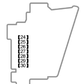
| 23 | ECU−B | 7,5 | Multi−mode manual transmission, daytime running light system, vehicle stability control system, gauges and meters, rear fog light |
| 24 | ECU−IG | 7,5 | Anti−lock brake system, vehicle stability control system, electric power steering system, electric cooling fan |
| 25 | BACK UP | 10 | Back−up lights, power door lock system, wireless remote control system, power windows, rear window defogger, tachometer, air conditioning system, heater system |
| 26 | WIP | 20 | Windshield wiper and washer, rear window wiper and washer |
| 27 | ACC | 15 | Power outlet, audio system |
| 28 | IG1 | 7,5 | Windshield wiper and washer, rear window wiper and washer, anti−lock brake system, electric power steering system, electric cooling fan, back−up lights, power door lock system, wireless remote control system, power windows, rear window defogger, tachometer, air conditioning system, heater system |
| 29 | IG2 | 15 | Multiport fuel injection system/sequential multiport fuel injection system, SRS airbag system, gauges and meters, daytime running light system, multi−mode manual transmission |
| 30 | A/C | 7,5 | Air conditioning system, power heater |
Fuses (type B)
| Fuse | Ampere rating [A] | Description | |
| 31 | AM1 | 40 | “ACC”, “WIP”, “ECU−IG”, “BACK UP” fuses |
| 32 | PWR | 30 | Power windows |
| 33 | HTR | 40 | Heater system, air conditioning system, “A/C” fuse |
| 34 | AMT | 50 | Multi−mode manual transmission |
| 35 | RADIATOR | 30* | Electric cooling fan |
| 40* | |||
| 36 | ABS NO.1 | 40 (without vehicle stability control system) | Anti−lock brake system and vehicle stability control system |
| VSC NO.1 | 50 (with vehicle stability control system) | Anti−lock brake system and vehicle stability control system | |
| 37 | EMPS | 50 | Electric power steering system |
| ∗: Replace the fuse with one of the same ampere rating as the original | |||
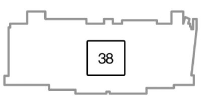
Fuse (type C)
| Fuse | Ampere rating [A] | Description | |
| 38 | ALTERNATOR | 120 | Charging system, “EPS”, “ABS (without vehicle stability control system)”, “VSC (with vehicle stability control system)”, “RADIATOR”, “AM1”, “HTR”, “PWR”, “D/L”, “DEF”, “TAIL”, “STOP”, “OBD”, “ECU−B” fuses |
WARNING: Terminal and harness assignments for individual connectors will vary depending on vehicle equipment level, model, and market.