Volkswagen Passat B5 (1996 – 2005) – fuse box diagram
Year of production: 1996, 1997, 1998, 1999, 2000, 2001, 2002, 2003, 2004, 2005
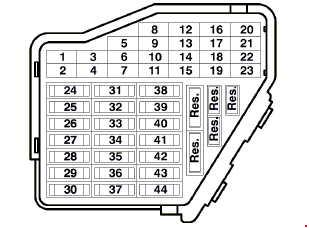
Left cockpit fuse assignment
| № |
A |
Circuits protected |
| 1 | 5 | Heated washer nozzle |
| 2 | 10 | Turn signal system |
| 3 | – | Not used |
| 4 | 5 | License plate light |
| 5 | 10 | Power Seats, air conditioning, telematics, Multi‐Function Steering Wheel, Power sunroof, mirror adjustment, HomeLink |
| 6 | 5 | Comfort module comfort system |
| 7 | 10 | ABS, Cruise Control system, Engine Control Unit |
| 8 | 5 | Automatic headlight beam adjusting |
| 9 | 5 | Parking aid |
| 10 | 5 | CD-Changer Unit, Telematics, Multi‐Function Steering Wheel, Navigation, Radio |
| 11 | 5 | Power Seats with Memory |
| 12 | 10 | B+ (battery positive voltage) for Data Link Connector (DLC) |
| 13 | 10 | Brake lights |
| 14 | 10 | Comfort module system |
| 15 | 10 | Instr. cluster, air conditioning, automatic transmission |
| 16 | 5 | ABS, Steering Angle Sensor |
| 17 | 10 15 |
Power outlet, Telematics |
| 18 | 10 | Right headlight, high beam |
| 19 | 10 | Left headlight, high beam |
| 20 | 15 | Right headlight, low beam |
| 21 | 15 | Left headlight, low beam |
| 22 | 5 | Parklight, right |
| 23 | 5 | Parklight, left |
| 24 | 25 | Wiper system |
| 25 | 30 | Fresh air blower, recirculating control, air conditioning, Power sunroof |
| 26 | 30 | Rear window defogger |
| 27 | 15 | Rear window wiper system |
| 28 | 20 | Fuelpump (FP) |
| 29 | 20 | Engine Control Unit, Coolant Fan |
| 30 | 20 | Sunroof |
| 31 | 15 | Back‐up lights, cruise control system, automatic transmission, Mirror adjustments, diagnostic |
| 32 | 20 | Engine Control Module (ECM), cruise control system |
| 33 | 15 | Cigarette lighter |
| 34 | 15 | Engine Control Module (ECM), injectors |
| 35 | 30 | Trailer socket |
| 36 | 15 | Fog lights |
| 37 | 20 | Radio system, Navigation |
| 38 | 15 | Comfort module system |
| 39 | 15 | Emergency flasher system |
| 40 | 25 | Dual horn |
| 41 | 25 | Telematics |
| 42 | 25 | ABS |
| 43 | 15 | Engine Control Module (ECM) |
| 44 | 30 | Heated seats |
Relay and fuse arrangements
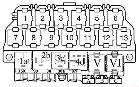
| Relay arrangement on thirteenfold auxiliary relay panel above relay panel | ||
| 1 | Coolant Fan Control (FC)‐A/C Relay (373) | |
| 2 | Sun-Roof Relay (79) | |
| 3 | A/C Clutch Relay (267) A/C Clutch Relay (384) |
|
| 4 | Daytime Running Lights Change‐Over Relay (173) | |
| 5 | Taxi Alarm Relay High Beam Headlight Relay Emergency Flasher Relay |
|
| 6 | Selector Lever Light Relay | |
| 7 | Fog Light Relay (381) | |
| 8 | Control Module for Multi‐function steering wheel (451) Control Module for Multi‐function steering wheel (452) |
|
| 9 | Control Module for Multi‐function steering wheel (451) Control Module for Multi‐function steering wheel (452) |
|
| 10 | Brake Booster Relay (373) | |
| 11 | Taxi Alarm Relay Emergency Flasher Relay (200) |
|
| 12 | Dual Horn Relay (53) Taxi Alarm Relay |
|
| 13 | Park/Neutral Position (PNP) Relay (175) Starting Interlock Relay‐Clutch Position (53) |
|
| Fuses at thirteenfold relay-panel | ||
| A | 25 | Fuse for Taxi |
| B | 20 | Fuse for Taxi |
| B | 10 | High Beam Headlight left, |
| C | 15 | Fuse for Brake System Vacuum Pump |
| D | 20 | Fuse for Power Outlet (12 V) Rear Console |
| E | 5 | Fuse for Taxi |
| E | 10 | High Beam Headlight right, |
| Relay locations on relay panel | ||
| 1a | Dual Horn Relay (53) | |
| 2b | Load Reduction Relay (370) | |
| 3c | Not used | |
| 4d | Fuel Pump (FP) Relay (372) (409) | |
| V | Wiper/Washer Intermittent Relay (377) (389) Wiper/Washer Intermittent Relay/Rainsensor (192) |
|
| VI | Wiper/Washer Intermittent Relay (377) (389) Wiper/Washer Intermittent Relay/Rainsensor (192) |
|
| Fuses on relay pane | ||
| A | 20 | Fuse for 12v socket I in luggage compartment |
| B | 20 | Fuse for 12v socket II in luggage compartment |
| C | 10 | Fuse for Taxi |
| *Numbers in parentheses indicate production control number stamped on relay housing. | ||
Relay arrangements on eightfold (eight posion) auxiliary relay panel behind relay panel
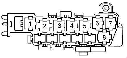
| Relay locations on relay panel | |
| 1 | Not used |
| 2 | Not used |
| 3 | Coolant Fan Control (FC) Relay 80 W (373) |
| 4 | Not used |
| 5 | First Speed Coolant Fan Control (FC) Relay (373) |
| 6 | Coolant Fan Control (FC) Relay (373) |
| 7 | Relay for ABS with ESP (373) |
| 8 | Coolant Fan Control (FC) Relay (370) |
| Fuses at eighthold auxiliary relay panel | |
| 30A | ABS Hydraulic Pump Fuse |
| 30A | Power Window Fuse |
| 30A 40A 60A |
Coolant Fan Fuse |
| 5A | Coolant Fan Fuse |
| 30A 50A |
ABS Hydraulic Pump Fuse |
| 30A | Power Seat Circuit Breaker ‐ Passenger’s Seat |
| 30A | Power Seat Circuit Breaker ‐ Driver’s Seat |
| 30A | Alarm System with Anti‐Theft warning system ‐ Telematics |
| 15A | Alarm System with Anti‐Theft warning system |
| *Numbers in parentheses indicate production control number stamped on relay housing. | |
Relay and fuse arrangements on Relay Panel
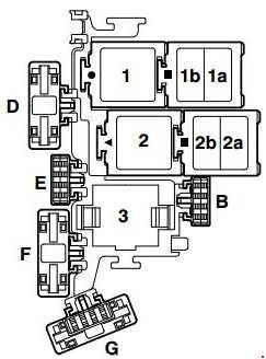
| № | A |
Circuits protected |
| B | 10 | Fuse for Injectors (S116) |
| B | 5 | Fuse for Auxiliary Engine Coolant (EC) Pump |
| D | 50 | Fuse for Secondary Air Pump (S130) |
| E | 40 | Fuse for Ignition coil termial (S115) |
| F | 5 | Engine control Module (ECM) Fuse (S102) |
| G | 10 | Engine Electronics Fuse (S282) |
| 1 | Motronic Engine Control Module Power Supply Relay (167), engine code BDP | |
| 2 | Secondary Air Injection (AIR) Pump Relay (373), (100) | |
| 3 | Motronic Engine Control Module Power Supply Reay (429), (219) Auxiliary Engine Coolant (EC) Pump Relay (53), (411) |
|
WARNING: Terminal and harness assignments for individual connectors will vary depending on vehicle equipment level, model, and market.