VW Transporter T5 – fuse box diagram
Year of production: 2003, 2004, 2005, 2006, 2007, 2008, 2009, 2010, 2011, 2012, 2013, 2014
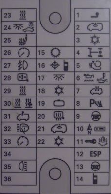
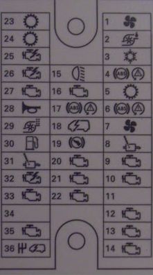
1st raw basic
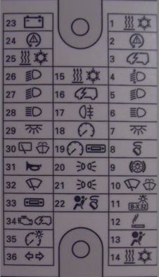
| Fuse | Ampere rating [A] | Description |
| 1 | 25 | Heater A/C |
| 30 | ||
| 2 | 5 | Steering position sensor |
| 3 | 10 | Multifunction control module1 |
| 4 | 10 | Headlamp adjustment |
| 5 | 15 | Headlamp |
| 6 | 15 | Headlamp |
| 7 | 15 | Multifunction control module1 (interior lamp) |
| 8 | 5 | Data link connector (DLC) |
| 9 | 15 | Brake pedal position |
| 10 | 10 | Windscreen wipers (rear) |
| 11 | 5 | Licence plate lamp |
| 12 | 15 | Cigarette lighter |
| 13 | 5 | SRS control module |
| 14 | 30 | Auxiliary heather, heather / A/C |
| 15 | 7,5 | Air conditioning |
| 16 | 5 | Multifunction control module 1 |
| 17 | 5 | Rear fog lamps |
| 18 | 5 | Instrumentation control module |
| 19 | 5 | Audio unit, Instrumentation control module1, navigation system |
| 20 | 5 | Side lamp left, LH Stop lamp, LH Tail lamp |
| 21 | 5 | Side lamp left, RH Stop lamp, RH Tail lamp |
| 22 | 10 | Airbag assembly deactivation warning lamp, (DLC), Instrumentation control module |
| 23 | 25 | Starter motor |
| 40 | Starter motor (some models with M/T) | |
| 24 | 5 | Steering position sensor |
| 25 | 5 | Air conditioning |
| 26 | 30 | Headlamp switch |
| 27 | 15 | Headlamp Right |
| 28 | 15 | Headlamp high beam warning lamp, Headlight Right |
| 29 | 10 | Load area door signal relay |
| 30 | 10 | Heated windscreen washer jets, rear screen wiper motor |
| 31 | 30 | Multifunction control module 1 (Horn) |
| 32 | 25 | Multifunction control module 1 (windscreen wiper motor) |
| 33 | 15 | Audio unit, Navigation system, Traffic information control module |
| 34 | 25 | Automatic transmission, Fuse box/relay plate engine bay 1 (F3, F12, F14-F17, F19, F20, F24) |
| 35 | 5 | Instrument illumination |
| 36 | 25 | Multifunction control module1 (Indicators) |
Second raw Options
At the engine bay close to the battery (remove the battery cover)
Under the passenger seat
| Fuse | Ampere rating [A] | Circuit |
| F1 | 15 | Auxiliary power socket(s) (some models) |
| F2 | 15 | Auxiliary power socket(s) (some models) |
| F3 | 15 | Auxiliary power socket(s) (some models) |
| F4 | 15 | Refrigerator box (camper van), special vehicle equipment |
| F5 | 5 | Aerial module |
| F6 | 25 | Auxiliary heater |
| F7 | 30 | Heater/AC blower motor (ATC) |
| F8 | — | — |
| F9 | — | — |
| F10 | — | — |
| F11 | 40 | Door function control module, right rear (some models) |
| F12 | 80 | Auxiliary battery (some models) |
| Split charge relay (some models) |
| Location | Component |
| 1 | — |
| 2 | Split charge relay (with auxiliary battery) |
| 3 | Special vehicle equipment |
| 4 | Special vehicle equipment |
| 5 | Special vehicle equipment |
NOTE: Fuses F1-F7/F11/F12 – During assembly these fuses may be fitted in alternative positions, depending on vehicle specification.
WARNING: Terminal and harness assignments for individual connectors will vary depending on vehicle equipment level, model, and market.