VW Golf mk5 – fuse box
Fuse box in passenger compartment
 Volkswagen Golf 5 – fuse box passenger compartment
| Fuse |
Ampere rating [A] |
Protected circuit |
| 1 |
10 |
Data Link Connector (DLC) |
| 2 |
10 |
Ani-lock breake system (ABS) |
| 3 |
10 |
Power steering |
| 4 |
5 |
Heated seats, heater/air conditioning (A/C) |
| 5 |
5 |
Breake pedal position (BPP) switch, clutch position potentiometr |
| 6 |
5 |
Databus connection, engine management, instrumention control module |
| 7 |
5 |
Headlamp level control module |
| 8 |
5 |
Interrior rear view mirror |
| 9 |
5 |
Four wheel drive control module |
| 10 |
5 |
Telephone |
| 11 |
5 |
Trailer control module |
| 12 |
10 |
Door function control module, driver, passenger |
| 13 |
10 |
Data Link Connector (DLC), light switch |
| 14 |
10 |
Breake pedal position (BPP) switch |
| 15 |
7,5 |
Multifunction control module 1 |
| 16 |
10 |
Heater/air conditioning (A/C) |
| 17 |
5 |
Audio system, windscreen wiper rain sensor |
| 18 |
30 |
Parking aid control module |
| 19 |
— |
Not used |
| 20 |
5 |
Ani-lock breake system (ABS) – Taves Mk60 |
| 21 |
— |
Not used |
| 22 |
40 |
Heater/air conditioning (A/C) |
| 23 |
30 |
Electric windows |
| 24 |
20 |
Cigarette lighter |
| 25 |
25 |
Multifunction control module 1 |
| 26 |
30 |
Charging socket |
| 27 |
15 |
Engine management |
| 28 |
— |
Not used |
| 29 |
10 |
Engine management |
| 30 |
5 |
Airbag |
| 31 |
5 |
Reversing lamp |
| 32 |
30 |
Electric windows |
| 33 |
25 |
Sunroof |
| 34 |
15 |
Electric seats |
| 35 |
5 |
Alarm system |
| 36 |
20 |
Headlamp washers |
| 37 |
30 |
Heated seats |
| 38 |
— |
Not used |
| 39 |
— |
Not used |
| 40 |
40 |
Heater/air conditioning (A/C) |
| 41 |
20 |
Rear screen wash/wipe system |
| 42 |
20 |
Windscreen washers |
| 43 |
15 |
Trailer control module |
| 44 |
20 |
Trailer control module |
| 45 |
15 |
Trailer control module |
| 46 |
5 |
Heater/air conditioning (A/C), windscreen washers jet heaters |
| 47 |
5 |
Heater/air conditioning (A/C) |
| 48 |
7,5 |
Electric seats, steering column adjustment |
| 49 |
5 |
Light switch |
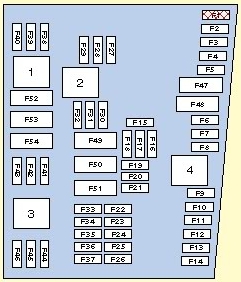
Fuse box in engine compartment
 Volkswagen Golf mk5 – fuse box engine compartment
| Fuse |
Ampere rating [A] |
Protected cirucuit |
| F1 |
30 |
Ani-lock breake system (ABS) |
| F2 |
30 |
Ani-lock breake system (ABS) |
| F3 |
20 |
Multifunction control module 2 |
| F4 |
5 |
Multifunction control module 2 |
| F5 |
20 |
Horn |
| F6 |
20 |
Engine management |
| F7 |
5 |
Breake pedal position (BPP) switch, clutch position potentiometr |
| F8 |
10 |
Engine coolant blower motor control module, engine management |
| F9 |
10 |
Engine management |
| F10 |
10 |
Engine management |
| F11 |
25 |
Engine management – petrol |
| 30 |
Engine management – diesel |
| F12 |
15 |
Engine management |
| F13 |
20 |
Automatic transmission (AT) |
| F14 |
— |
Not used |
| F15 |
40 |
Starter motor |
| F16 |
15 |
Steering column function control module |
| F17 |
10 |
Instrument panel |
| F18 |
— |
Not used |
| F19 |
15 |
Audio system, navigation system |
| F20 |
10 |
Telephone |
| F21 |
— |
Not used |
| F22 |
— |
Not used |
| F23 |
10 |
Cruise control |
| F24 |
10 |
Databus connection |
| F25 |
— |
Not used |
| F26 |
5 |
Engine management – diesel |
| 10 |
Engine management – petrol |
| F27 |
10 |
Cranckcase breather heater |
| F28 |
20 |
Automatic transmission (AT) |
| F29 |
20 |
Engine management |
| F30 |
20 |
Heater/air conditioning (A/C) |
| F31 |
25 |
Windscreen wipers |
| F32 |
10 |
Engine management |
| F33 |
15 |
Fuel lift pump |
| F34 |
— |
Not used |
| F35 |
— |
Not used |
| F36 |
— |
Not used |
| F37 |
— |
Not used |
| F38 |
10 |
Headlamps adjustment |
| F39 |
5 |
Engine oil temperature sensor, instrument panel |
| F40 |
20 |
Fascia fuse box /relay plate (F1 – F11/F29 – F31) |
| F41 |
— |
Not used |
| F42 |
5 |
Engine management – petrol |
| 10 |
Engine management – diesel |
| F43 |
— |
Not used |
| F44 |
— |
Not used |
| F45 |
— |
Not used |
| F46 |
— |
Not used |
| F47 |
40 |
Multifunction control module 1 |
| F48 |
40 |
Multifunction control module 1 |
| F49 |
— |
Not used |
| F50 |
40 |
Audio system |
| F51 |
50 |
Glow plug control module |
| F52 |
50 |
Multifunction control module 1 |
| F53 |
50 |
Fascia fuse box /relay plate 1 (F32 – F37), fascia fuse box /relay plate 2 (F4) |
| F54 |
— |
Not used |
Relays
| Relays |
Description |
| 1 |
Ignition main circuits relay 2 |
| 2 |
Starter motor relay |
| 3 |
Fuel pump relay – 1,4 (BCA)/1,6 (BGU) |
| 4 |
Ignition main circuits relay 1 |
WARNING: Terminal and harness assignments for individual connectors will vary depending on vehicle equipment level, model, and market.