Hyundai XG 350 – fuse box diagram
Year of production:
Engine compartment
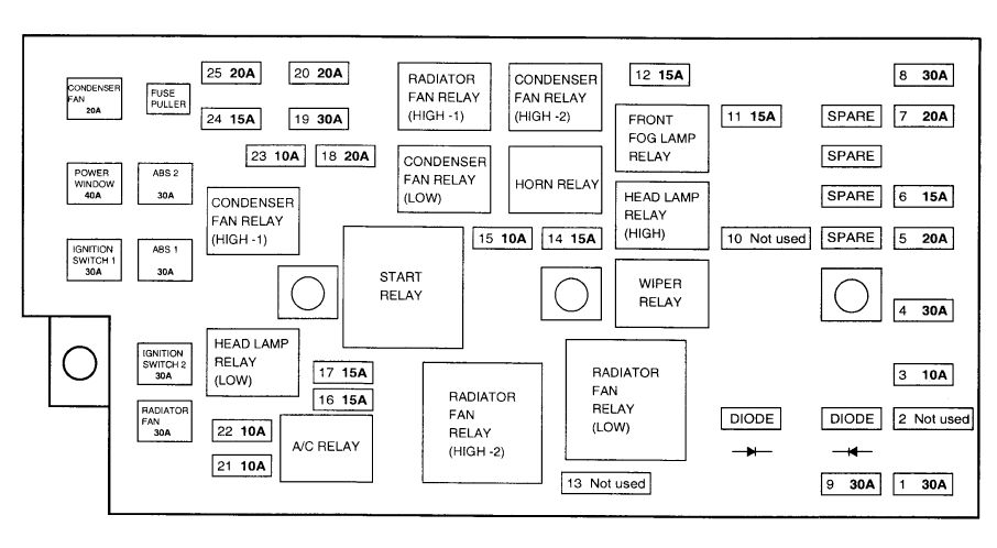
| Description | A | Protected component | |
| CONDENSER | 20 | Condenser fan motor | |
| POWER WINDOW | 40 | Power window | |
| IGNITION SWITCH 1 | 30 | Ignition switch (ACC, IG 1) | |
| ABS 1 | 30 | ABS control | |
| ABS 2 | 30 | ABS control | |
| IGNITION SWITCH 2 | 30 | Ignition switch (IG2, Start) | |
| RADIATOR | 30 | Radiator fan motor | |
| 1 | REAR DEFOGGER | 30 | Defogger relay |
| 2 | — | — | — |
| 3 | ECM | 10 | Generator, ECM |
| 4 | PASSENGER COMPARTMENT JUNCTION BLOCK 1 | 30 | Passenger compartment junction block (Fuse 1, 7, 17, 18, 19) |
| 5 | TAIL LAMP | 20 | Tail lamp relay |
| 6 | SUNROOF | 15 | Sunroof, Data link connector |
| 7 | POWER AMP | 20 | Speaker amp |
| 8 | PASSENGER COMPARTMENT JUNCTION BLOCK 2 | 30 | Passenger compartment junction block (Fuse 4, 20, 24, 25) |
| 9 | BLOWER | 30 | Blower control |
| 10 | — | — | — |
| 11 | FRONT FOG LAMP | 15 | Front fog lamps |
| 12 | DRL | 15 | DRL control, Siren |
| 13 | — | — | — |
| 14 | HEAD LAMP (High) | 15 | Head lamps (High) |
| 15 | HORN | 10 | Horn |
| 16 | EGR | 15 | ECM, Fuel pump relay, PCV, ISA, CKP |
| 17 | OXYGEN SENSOR | 15 | Oxygen sensor, CCV |
| 18 | IGNITION COIL | 20 | Ignition coil, Ignition failure sensor |
| 19 | MAIN | 30 | Engine control relay |
| 20 | A/T | 20 | AfT control relay, TCM |
| 21 | A/C COMPRESSOR | 10 | A/C control |
| 22 | INJECTOR | 10 | Injector |
| 23 | ABS | 10 | ABS, Cruise |
| 24 | HEAD LAMP (Low) | 15 | Head lamps (Low) |
| 25 | FUEL PUMP | 20 | Fuel pump relay – motor |
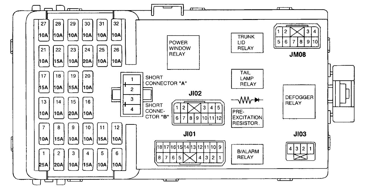
Passenger compartment
Front side
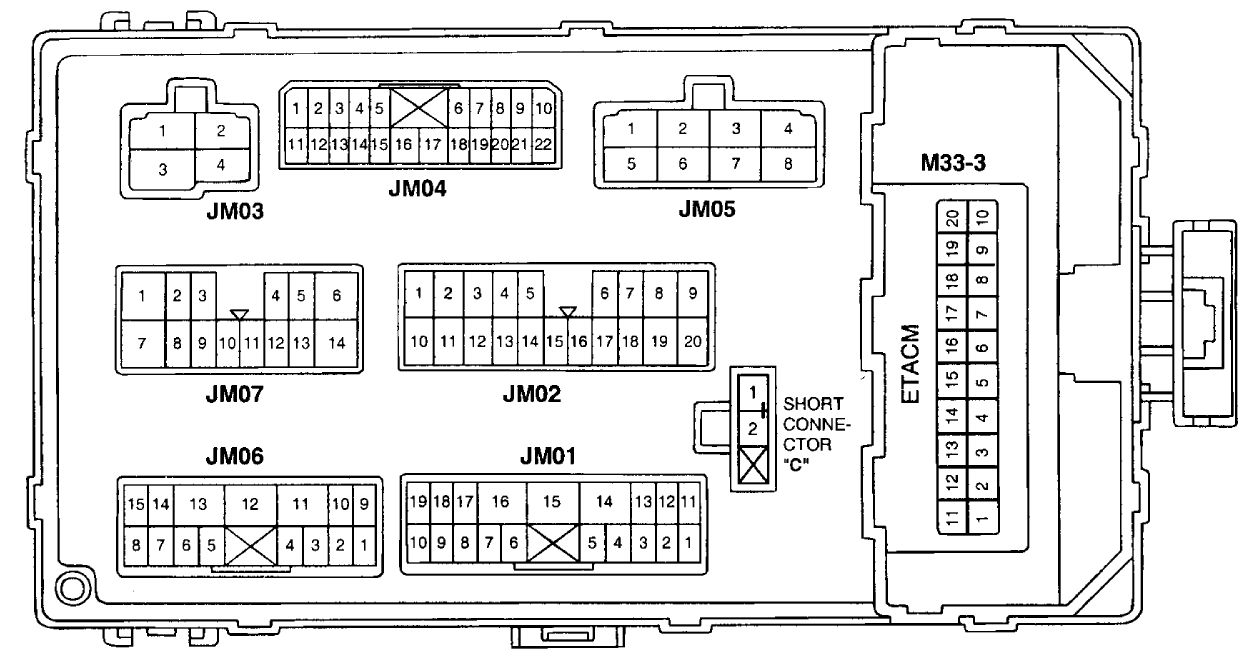
Backside
| Fuse | A | Protected components |
| 1 | 25 | Power seat |
| 2 | 20 | Seat warmer |
| 3 | 10 | Power steering control module |
| 4 | 15 | ETS relay |
| 5 | 10 | Head lamp, DRL, AQS sensor, Left(Right) head lamp leveling actuator |
| 6 | 10 | A/C switch, High blower relay |
| 7 | 10 | Hazard switch, Hazard relay |
| 8 | — | — |
| 9 | 10 | Cruise control, HLLD, Stop lamp |
| 10 | 10 | IMS control |
| 11 | 15 | Wiper & Washer |
| 12 | 10 | ETACM, Blower relay, sunroof, mirror, NC control |
| 13 | — | — |
| 14 | 10 | Audio |
| 15 | 20 | Cigarette lighter, Accessory socket |
| 16 | 10 | IMS switch, Driver door module |
| 17 | 15 | — |
| 18 | 10 | Rear fog lamp relay |
| 19 | 15 | Stop lamp switch |
| 20 | 10 | Room lamp, Trunk room lamp, Door lamp |
| 21 | 10 | Instrument cluster |
| 22 | 15 | SRS, PPD |
| 23 | 10 | TCM, Back-up lamps, Speed sensor, Transaxle range switch |
| 24 | 20 | Fuel filler door & Trunk lid opener, Driver(Assister) door module |
| 25 | 10 | ETACM, NC control, Audio, Clock, Cluster, Trip computer, Immobilizer |
| 26 | 10 | Front fog lamps, Tail, parking & license lamps, Short connector “C” |
| 27 | 10 | Stop lamp failure sensor |
| 28 | 10 | Clock, Instrument cluster, Immobilizer, Trip computer, TCS |
| 29 | 10 | ETACM, Hazard switch, Auto light |
| 30 | 10 | Rear defogger glass, NC control, Left(Right) outside mirror & Folding motor |
| 31 | 10 | Tail, Parking & license lamps, Left(Right) vanity lamp |
| 32 | 10 | Burglar alarm relay |
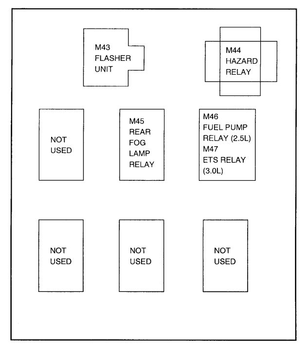
Relay box
WARNING: Terminal and harness assignments for individual connectors will vary depending on vehicle equipment level, model, and market.