Audi A2 (8Z; 1999 – 2005) – fuse box diagram
Year of production: 1999, 2000, 2001, 2002, 2003, 2004, 2005
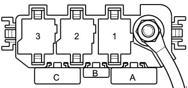
The location of the fuse box
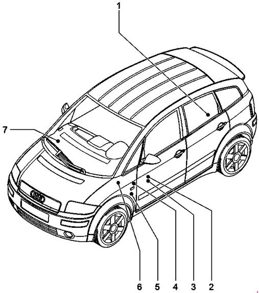
1 – Main fuse 150 A2 – Relay carrier (9-point)3 – Fuse box
4 – Relay carrier (6+6-point)
5 – Relay carrier (3-point)
6 – Connector point, A pillar, left
7 – Connector point, A pillar, right
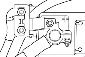
Main fuse
On battery
| № |
A |
Designation |
| S88 | 150 A | Strip fuse |
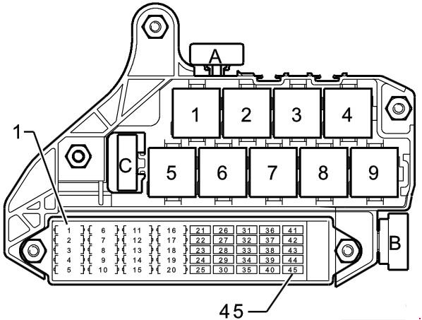
Relay carrier (9-point)
| № |
Designation | A |
| A | Multi-function steering wheel fuse (S326) | 1 |
| В | Additional heater fuse (S126) | 60 |
| C | Radiator fan control unit fuse (S142) | 40 |
| 1 | Control unit with display in dash panel insert | 10 |
| 2 | Navigation interface RadioVoltage stabiliser 2Aerial selection control unitOperating electronics control unit, navigationNavigation/TV tunerAmplifier | 20 |
| 3 | Voltage stabiliser | 20 |
| 4 | Radiator fanRadiator fan thermo-switch | 20 |
| 6 | Automatic intermittent wash/wipe relay Washer pump switch Intermittent wiper switch |
25 |
| 7 | Hazard warning light relay | 15 |
| 8 | Dual tone horn relay Horn/dual tone hom Sliding sunroof adjustment control unit |
25 |
| 10 | Trailer socket | 30 |
| 11 | 12 V socket | 20 |
| 12 | Cigarette lighter | 15 |
| 13 | Heated driver’s seat regulatorHeated front passenger’s seat regulator | 15 |
| 14 | Low heat output relay | 30 |
| 14 | Heater control unit | 20 |
| 15 | Air соnditioning system/Climatronic operating and display unit Heated rear window Heated rear window relay |
30 |
| 16 | Fresh air blower switch Fresh air blower control unit |
30 |
| 18 | Fuel pump (pre-supply pump) | 20 |
| 19 | Lambda probe heaterLambda probe 1 heater, downstream of catalytic converter Activated charcoal filter system solenoid valve 1 (pulsed) NOx sensor control unit |
20 |
| 20 | 4LV (injection system) control unit Ignition coil -1- with output stage Ignition coil -2- with output stage Ignition coil -3- with output stage Ignition coil -4- with output stage |
20 |
| 22 | Twin filament bulb for headlight, left | 10 |
| 23 | Bulb check warning unitHeadlight range control motor, right Twin filament bulb for headlight, right |
15 |
| 24 | Bulb check warning unitHeadlight range control motor, left Twin filament bulb for headlight, left |
15 |
| 25 | Mobile telephone operating electronics control unit Telephone/telem atics control unit Aerial amplifier, mobile telephone |
5 |
| 26 | Bulb check warning unit Tail light bulb, right Side light bulb, right |
5 |
| 27 | Bulb check warning unit Tail light bulb, left Side light bulb, left |
5 |
| 28 | Diagnostic connector | 10 |
| 29 | Diagnostic connector Reversing light switch | 15 |
| 30 | Brake light switch | 10 |
| 31 | Brake light switchHeater element (crankcase breather) (MPI engine, diesel engine)Air mass meterLow heat output relayHigh heat output relayCruise control system switchRadiator fan control unitAdditional air heater control unitExhaust gas recirculation valve | 10 |
| 32 | Glove box lightNumber plate light, left Number plate light, right |
10 |
| 33 | Heater element, left washer jet Heater element, right washer jet |
5 |
| 34 | Hazard warning light relay | 10 |
| 35 | Rear left fog light bulbFront and rear fog light switch | 15 |
| 36 | Anti-theft alarm system hornAir соnditioning system /Climatronic operating and display unitHeated rear window relayTank filler flap remote release switchInterior monitor switchConvenience system central control unit | 10 |
| 37 | Navigation system with CD drive control unit Parking aid control unit |
10 |
| 38 | Automatic anti-dazzle interior mirror | 10 |
| 38 | Compressor regulating valve, air conditioning system Heated rear window relay Fresh air/air recirculating flap switch Operating electronics control unit, navigation Electronic manual gearbox control unit Parking aid control unit Power steering control unit Navigation system with CD drive control unit Telephone/telematics control unit Ignition key withdrawal lock control unit Additional heating button (ECON)AmplifierHazard warning light switch |
10 |
| 39 | Door control unit, front passenger’s side Door control unit, rear right |
10 |
| 40 | Traction соntrol system warning lamp Traction control system switch ABS with EDL control unit Steering angle sender |
10 |
| 41 | Door control unit, driver’s side Door control unit, rear left |
10 |
| 42 | Anti-theft alarm ultra-sonic sensorConvenience system central control unit | 10 |
| 43 | Electronic manual gearbox control unit | 10 |
| 44 | Ignition key withdrawal lock solenoid valve Electronic manual gearbox control unit Handbrake warning lam p control unit Ignition key withdrawal lock control unit |
10 |
| 45 | Injector, cylinder 1Injector, cylinder 2 Injector, cylinder 3 Injector, cylinder 4Heater elem ent (crankcase breather) (FSI engine)Fuel pressure regulating valveInlet cam shaft tim ing adjustment valve -1-Fuel metering valveIntake manifold flap air flow control valve Map-controlled engine cooling thermostat |
15 |
| Relays | ||
| 1 | Consumer switch -off relay (J511) | |
| 4 | High heat output relay (J360) | |
| 5 | Dual tone horn relay (J4) | |
| 6 | Bulb check warning unit (K41) | |
| 7 | Bulb check warning unit (K41) | |
| 8 | Low heat output relay (J359) | |
| 9 | X contact relief relay (J59) | |
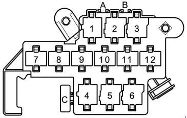
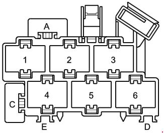
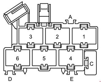
Relay carrier (6+6-point)
In footwell, front left
| № |
Designation | |
| 1* | Starter inhibitor and reversing light relay (J226) | |
| 2 | Autom atic interm ittent wash/wipe relay (J31) | |
| 3 | Autom atic interm ittent wash/wipe relay (J31) | |
| 4* | Gearbox hydraulic pump relay (J510) | |
| 5* | Ignition key withdrawal lock control unit (J557) | |
| 5** | Fuel pump relay (J17) | |
| 6* | Ignition key w ithdraw al lock control unit (J557) | |
| № |
Designation | A |
| A | Hydraulic pump relay fuse (S279) | 20 |
| C | ABS control unit fuse 1 (S123) | 60 |
| * – Only applies to engine code ANY ** – Only applies to engine codes BAD, BBY |
||
Relay carrier (3-point)
| № |
Designation | A |
| A* | Strip fuse for glow plugs (engine) (S39) | 40 |
| A** | Engine control unit fuse (S102) | 30 |
| A*** | Strip fuse for glow plugs (engine) (S39) | 60 |
| B* | Engine control unit fuse (S102) | 10 |
| B** | Air mass meter fuse (S74) | 5 |
| B*** | Engine control unit fuse (S102) | 10 |
| C | Fuse -1 – (30) (power steering) (S204) | 80 |
| Relays | ||
| 1* | Terminal 30 voltage supply relay (J317) | |
| 1** | Motronic current supply relay (J271) | |
| 1*** | Relay for glow plugs (J52) | |
| 2* | Automatic glow period control unit (J179) | |
| 2*** | Terminal 30 voltage supply relay (J317) | |
| – Only applies to engine code ATL ** – Only applies to engine code BAD *** – Only applies to engine codes AMF, ANY, BHC |
||
Connector point, A pillar, left
| № |
Designation | A |
| A | Electric w indow single fuse (front) (S37) | 30 |
| C | Seat adjustment fuse (lumbar support) (S45) | 10 |
Connector point, A pillar, right
| № |
Designation | A |
|
C |
Electric window single fuse 2 (rear) (S280) |
30 |
WARNING: Terminal and harness assignments for individual connectors will vary depending on vehicle equipment level, model, and market.