BMW X5 (E70) – (2006 – 2013) – fuse box diagram
Year of production: 2006, 2007, 2008, 2009, 2010, 2011, 2012, 2013
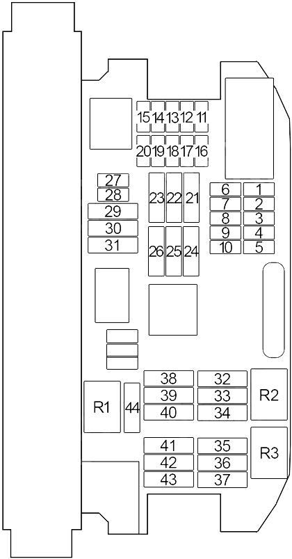
Passenger Compartment Fuse
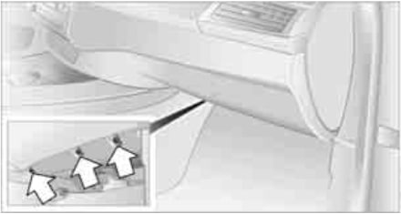
The fuses are located in the front passenger footwell on the underside of the instrument cluster.
1. Unscrew screws of footwell trim panel.
2. Lay the trim panel in the footwell.
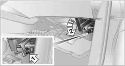
3. Release the screw, arrow 1, and fold the fuse carrier down, arrow 2.
| No. |
A |
Protected Component |
| 1 | 20 | Steering Column Adjustment Motor, Heating/Air Conditioning System |
| 2 | 10 | Glove Compartment Unlock Drive Unit, Glove Compartment Light (10.2009→) |
| 3 | 7.5 | Siren and Tilt Alarm Sensor |
| 4 | 10 | except N55: Digital Motor Electronics (DME) Module |
| 10 | N55: Integrated Supply Module | |
| 5 | 10 | Roof Function Control Centre |
| 6 | 10 | iDrive Controller, DVD-Changer, CD Changer, Video Selector Switch |
| 7 | 5 | Active Cruise Control, Longitudinal Dynamics Management, Tyre Pressure Control (RDC) |
| 8 | 7.5 | Vertical Dynamics Management (Front Left/Right Damper Satellite) |
| 9 | 15 | Horn Relay (Left/Right Horn) |
| 10 | 5 | Parking Brake, Car Access System |
| 11 | 20 | Independent Auxiliary Heater |
| 12 | 10 | Steering Column Switch Center |
| 13 | 15 | Transmission Control |
| 14 | 10 | Dynamic Drive |
| 15 | 10 | Gear Selector Switch |
| 16 | 10 | Driver’s Door Switch Block, Driver’s Side Outside Mirror, Passenger’s Side Outside Mirror |
| 17 | 5 | Central Information Display, Heating/Air Conditioning System (without Electrical Steering Column Adjustment), Active Video Switch (Japan) |
| 18 | 7.5 | Head-Up Display, E-Box Fan, Fuel Tank Vent Valve (→09.2011), Tank Vent Shutoff Valve (→09.2011) |
| 19 | 5 | Dynamic Stability Control (DSC), Roof Function Control Centre (without Sunroof) |
| 20 | 10 | Integrated Chassis Management (ICM), Servotronic (without ICM) |
| 21 | 30 | Rear Window Defogger |
| 22 | 5 | Left Headlight |
| 23 | 40 | Footwell Module |
| 24 | 40 | Active Steering |
| 25 | 5 | Right Headlight |
| 26 | 30 | →08.2008: Headlight Washer Pump |
| 25 | 08.2008→: Headlight Washer Pump | |
| 27 | 15 | →03.2010: Central Locking System |
| 20 | 04.2010→: Central Locking System | |
| 28 | 15 | Central Locking System |
| 29 | 40 | Rear Driver’s Side Power Window Motor |
| 30 | 30 | Central Locking System |
| 31 | 40 | Rear Passenger’s Side Power Window Motor |
| 32 | 40 | Air Suspension Compressor |
| 33 | 30 | Footwell Module |
| 34 | 30 | Footwell Module |
| 35 | 30 | N63, S63: Oxygen Sensors |
| 30 | N62: Crankshaft Sensor, Hot-Film Air Mass Meter, Intake Camshaft Sensor No.1, Exhaust Camshaft Sensor No.1, Oil Condition Sensor, Characteristic Map Thermostat, VANOS Solenoid Valve No.1 – intake, VANOS Solenoid Valve No.1 – exhaust | |
| 30 | N52: Electric Coolant Pump, Intake Camshaft Sensor, Exhaust Camshaft Sensor, VANOS Solenoid Valve – intake/exhaust, Characteristic Map Thermostat | |
| 36 | 30 | N63: VANOS Solenoid Valve No.2 – intake, VANOS Solenoid Valve No.2 – exhaust, Crankshaft Sensor, Blow-Off Valve (No.1, No.2), Hot-Film Air Mass Meter (No.1, No.2) |
| 30 | N62: Fuel Injectors (No.: 1, 2, 3, 4), Fuel Tank Vent Valve, Intake Camshaft Sensor No.2, Exhaust Camshaft Sensor No.2, VANOS Solenoid Valve No.2 – intake, VANOS Solenoid Valve No.2 – exhaust |
|
| 30 | N52: Fuel Injectors, Ignition Coils, Interference Suppression Capacitor for Ignition Coils | |
| 37 | 20 | Rear Wiper Motor |
| 38 | 30 | N57: SCR Load Relay |
| 30 | N62: Terminal 15 Power-Saving Relay | |
| 30 | N63: Fuse: “06” (Coolant Pump for Intercooler) | |
| 39 | 40 | Car Access System |
| 40 | 30 | Dynamic Stability Control (DSC) |
| 41 | 7.5 | N63, S63: Coolant Pump for Charge Air Cooler No.2, Radiator Shutter Drive Unit |
| 7.5 | N52, N62: Air Mass Flow Sensor, Radiator Shutter Drive Unit | |
| 42 | 30 | N63, S63: Digital Motor Electronics (DME) Module, Coolant Pump for Intercooler, Volume Control Valve, Wastegate Valve Pressure Converter (No.1, No.2) |
| 30 | N62: Digital Motor Electronics (DME) Module, Variable Valve Timing Gear Control Unit, Fuel Injectors (No.: 5, 6, 7, 8) | |
| 30 | N52: Digital Motor Electronics (DME) Module, Fuel Tank Vent Valve, Crankshaft Sensor, Air Mass Flow Sensor, DISA Actuator No.1, DISA Actuator No.2, Crankshaft Breather Heating | |
| 43 | 30 | N63, S63: Intake Camshaft Sensor (No.1, No.2), Exhaust Camshaft Sensor (No.1, No.2), Oil Condition Sensor, Fuel Tank Vent Valve, Characteristic Map Thermostat, Coolant Pump for Intercooler |
| 30 | N52, N62: Oxygen Sensors, Oil Condition Sensor (N52) | |
| 44 | 30 | Front Wiper Motor |
| Non-Replaceable | ||
| 45 | 60 | Electric Fan Cut-Out Relay (Electric Fan) |
| 46 | 40 | Dynamic Stability Control (DSC) |
| 47 | 40 | N57, M57US: Fuel Heater |
| 40 | N52: Electric Coolant Pump | |
| 48 | 40 | Blower Output Stage |
| 49 | – | – |
| Relay | ||
| R1 | Wiper (Relay No.2) | |
| R2 | Air Suspension Compressor | |
| R3 | Rear Wiper | |
Petrol Engines:
- N52B30 – 3.0l. (3.0si & xDrive30i)
- N55B30 – 3.0l. (xDrive35i)
- N55B30A – 3.0l. (xDrive40i )
- N62B48 – 4.8l. (4.8i & xDrive48i)
- N63B44 – 4.4l. (xDrive50i)
- S63B44 – 4.4l. (X5 M)
Diesel Engines:
- M57TU2D30 – 3.0l. (3.0d, xDrive30d, 3.0sd, xDrive35d)
- N57D30OL – 3.0l. (xDrive30d)
- N57D30TOP – 3.0l. (xDrive40d)
- N57D30S1 – 3.0l. (X5 M50d)
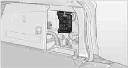
Luggage Compartment Fuse Box
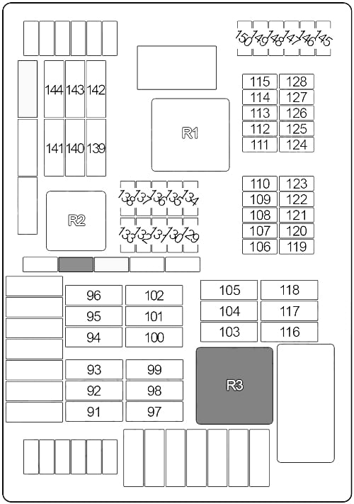
| No. |
A |
Protected Component |
| 91 | 30 | Rear Right Electric Auxiliary Heater |
| 92 | 25 | →03.2011: Transfer Box Control Unit |
| 30 | 04.2011→: Transfer Box Control Unit | |
| 93 | 30 | Rear Axle Transverse Torque Distribution (QMVH) (without 3rd Row of Seats) |
| 40 | 3rd Row of Seats Auxiliary Heater Control Unit | |
| 94 | 30 | Parking Brake Control Unit |
| 95 | 30 | Rear Left Electric Auxiliary Heater |
| 96 | 40 | Footwell Module |
| 97 | 20 | →09.2008: Fuel Pump Relay (without Electronically Controlled Fuel Pump), Fuel Pump Control (EKPS) (with Electronically Controlled Fuel Pump) |
| 98 | 15 | Rear Compartment Blower Motor |
| 99 | 40 | 03.2007→: Boot Lid Lift |
| 100 | 20 | Rear Left Seat Heating Module (with Rear Compartment Air Conditioning), Terminal 15 Power-Saving Relay (without Rear Compartment Air Conditioning) |
| 101 | 30 | Driver’s Seat Module, Driver’s Seat Adjustment Switch, Driver’s Lumbar Support Switch |
| 102 | 30 | Passenger’s Seat Module, Passenger’s Seat Adjustment Switch, Passenger’s Lumbar Support Switch |
| 103 | 30 | →09.2009: Audio Amplifier |
| 40 | 10.2009→: Audio Amplifier | |
| 104 | 25 | Electrically Operated Towing Hitch |
| 105 | 20 | 10.2008→: Fuel Pump Relay (without Electronically Controlled Fuel Pump), Fuel Pump Control (EKPS) (with Electronically Controlled Fuel Pump) |
| 106 | 7.5 | Vertical Dynamics Management (Rear Left/Right Damper Satellite) |
| 107 | 10 | Electronic Ride Height Control, Rear Compartment Display (→03.2012), Tyre Pressure Control – RDC (04.2012→) |
| 108 | 5 | Reversing Camera, Rear Seat Entertainment, Headset Socket, Headset Connection Module |
| 109 | 10 | →03.2012: Satellite Receiver (→03.2011), Digital Tuner (USA) (→09.2009), Tyre Pressure Control – RDC (04.2010→) |
| 15 | 04.2012→: Active Sound Design (ASD) | |
| 110 | 7.5 | →02.2009: Luggage Compartment Light, Noise Suppressor Filter, Interface Box High (ULF-SBX-H), Telematics (TCU), Interface Box (ULF-SBX), Telephone Eject Box, USB Hub |
| 5 | 03.2009→: Luggage Compartment Light, Noise Suppressor Filter, Interface Box High (ULF-SBX-H), Combox Media, Interface Box (ULF-SBX), Telephone Eject Box, USB Hub | |
| 111 | 20 | Front Cigar Lighter |
| 112 | 5 | Driver’s Seat Heating Module, Passenger’s Seat Heating Module, Terminal 15 Power-Saving Relay, Rear Left Seat Heating Module, Rear Right Seat Heating Module |
| 113 | 20 | Luggage Compartment Charging Socket, Centre Console 12V Socket |
| 114 | 5 | Roof Function Control Centre, Park Distance Control (PDC), All-Round Vision Camera, Camera-Based Driver Support Systems |
| 115 | 20 | Rear Cigar Lighter, Rear Socket Outlet |
| 116 | 20 | Trailer Socket |
| 117 | 20 | Roof Function Control Centre (Sunroof) |
| 118 | – | – |
| 119 | 10 | →09.2009: Video Module |
| 5 | 10.2009→: Video Module | |
| 120 | 5 | Vertical Dynamics Management |
| 121 | 5 | Boot Lid Lift |
| 122 | 5 | Diagnostic Module for Fuel Tank Leakage |
| 123 | 5 | Rear Axle Transverse Torque Distribution (QMVH) |
| 124 | 5 | Junction Box Electronics (JBE) |
| 125 | 5 | Transfer Box Control Unit |
| 126 | 5 | Rear Compartment Air Conditioning Control Unit |
| 127 | 5 | Electric Fan Cut-Out Relay |
| 128 | 5 | Exhaust Flap |
| 129 | 5 | Parking Brake Control Unit, Aerial Diversity |
| 130 | 15 | S63, N63: Coolant Pump for Charge Air Cooler No. 2, Coolant Pump for Intercooler (N63; 10.2008→) |
| 15 | N57: Coolant Pump for Charge Air Cooler | |
| 131 | 5 | →09.2009: Instrument Cluster, Diagnostic Connector OBD II |
| 5 | 10.2009-03.2012: Active Sound Design (ASD) | |
| 132 | 7.5 | Audio Amplifier Active Sound Design – ASD (10.2009→), Comfort Access Control Unit (бесключевой доступ), Passenger’s Side Outer Door Handle Electronic Module, Rear Left Electronic Outer Door Handle Module, Rear Right Electronic Outer Door Handle Module |
| 133 | – | – |
| 134 | 5 | Steering Column Switch Center, Diagnostic Connector OBD II (10.2009→), Instrument Cluster (10.2009→) |
| 135 | 20 | Boot Lid/Tailgate Automatic Soft-Close Drive |
| 136 | 5 | Telematics (TCU), Telephone Eject Box |
| 5 | Combox Media | |
| 137 | 5 | Navigation System |
| 138 | 10 | Electrically Operated Towing Hitch |
| 139 | 20 | Rear Right Seat Heating Module |
| 140 | 20 | Driver’s Seat Heating Module |
| 141 | 20 | Passenger’s Seat Heating Module |
| 142 | 20 | →09.2009: CCC/M-ASK or CHAMP |
| 20 | 10.2009→: Car Information Computer (CIC) | |
| 143 | 25 | →03.2010: Trailer Module |
| 20 | 04.2010→: Trailer Module | |
| 144 | 25 | →03.2010: Trailer Module |
| 20 | 04.2010→: Trailer Module | |
| 145 | 10 | Driver’s Door Automatic Soft-Close Drive |
| 146 | 10 | Passenger’s Door Automatic Soft-Close Drive |
| 147 | 10 | Rear Left Automatic Soft-Close Drive |
| 148 | 10 | Rear Right Automatic Soft-Close Drive |
| 149 | 7.5 | Driver’s Seat Adjustment Switch |
| 150 | 7.5 | Passenger’s Seat Adjustment Switch |
| Relay | ||
| R1 | Terminal 15 | |
| R2 | Bistable Relay | |
| R3 | Terminal 30G | |
| Soft Close Automatic | ||
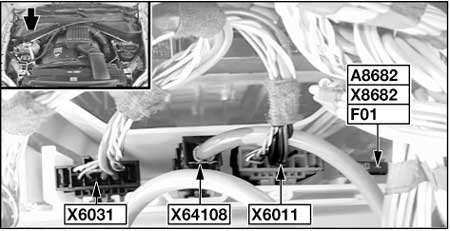
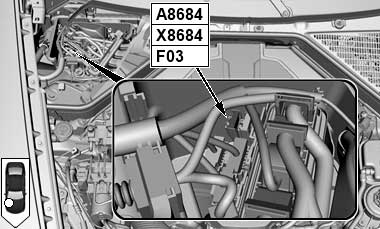
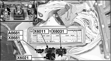
Engine Compartment Fuse Holder (N52)
| No. |
A |
Protected Component |
| 01 | 40 | Valvetronic Relay |
Engine Compartment Fuse Box (N55)
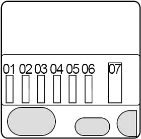
| No. |
A |
Protected Component |
| 01 | 15 | Digital Motor Electronics (DME) Module |
| 02 | 20 | Digital Motor Electronics (DME) Module |
| 03 | 15 | Digital Motor Electronics (DME) Module, Exhaust Flap, Radiator Shutter Drive Unit |
| 04 | 15 | Digital Motor Electronics (DME) Module, Fuel Injectors |
| 05 | 20 | Digital Motor Electronics (DME) Module, Ignition |
| 06 | 40 | Digital Motor Electronics (DME) Module, Valvetronic |
| 07 | 50 | Electric Coolant Pump |
Engine Compartment Fuse Holders (N62)
| No. |
A |
Protected Component |
| 01 | 40 | Valvetronic Relay |
| 02 | 40 | Valvetronic Relay No.2 |
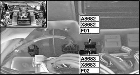
Engine Compartment Fuse Holders (N63, S63)

| No. |
A |
Protected Component |
| 01 | 30 | →04.2013: Coolant Pump for Intercooler, Digital Motor Electronics (DME) Module |
| 30 | 05.2013→: Digital Motor Electronics (DME) Module, Fuse: “03” | |
| 02 | 30 | Ignition Coils, Interference Suppression Capacitor for Ignition Coils |
| No. |
A |
Protected Component |
| 03 | 5 | 05.2013→: Turbocharger Coolant Pump |
| No. |
A |
Protected Component |
| 06 | 15 | Coolant Pump for Intercooler |
Engine Compartment Fuse Box (N57, M57)
| No. |
A |
Protected Component |
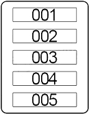
| 001 | 20 | M57: Boost Pressure Adjuster No.1, Camshaft Hall-Effect Sensor No.1, Rail Pressure Control Valve, Volume Control Valve, Throttle Valve |
| 20 | N57: Nitrogen Oxide Sensor Before SCR Catalytic Converter, High-Pressure Stage Charging Pressure Actuator (VNT No.1, 2), LP-EGR Valve, Camshaft Hall-Effect Sensor No.1, Changeover Valve Low Pressure Compressor Bypass Flap, Turbine Control Valve, Rail Pressure Control Valve, Volume Control Valve, Throttle Valve | |
| 002 | 20 | M57: Exhaust Gas Recirculation Solenoid Valve, Crankcase Breather Heating, Engine Mount Electrical Changeover Valve, Swirl Flaps Electric Changeover Valve, Oxygen Sensor before Catalytic Converter, Preheating Control Unit, Oil Condition Sensor |
| 20 | N57: Wastegate Valve, Compressor Bypass Valve, Exhaust Gas Recirculation Solenoid Valve, Engine Mount Electrical Changeover Valve, Swirl Flaps Electric Changeover Valve, Oxygen Sensor before CatalyticConverter, Preheating Control Unit, Oil Condition Sensor | |
| 003 | 30 | M57, N57: Digital Diesel Electronics (DDE) Control Unit |
| 004 | 30 | M57: Radiator Shutter Drive Unit |
| 10 | N57: Crankcase Breather Heating, SCR Load Relay, Radiator Shutter Drive Unit, Nitrogen Oxide Sensor after SCR Catalytic Converter, Transfer Pump, SCR Delivery Module, Passive Tank Fill Level Sensor | |
| 005 | 10 | M50d: Coolant Pump Relay, High-Pressure Compressor No.2 – Changeover Valve for Recirculated-Air Flap, Pressure Converter for Wastegate Valve, Changeover Valve of Turbine Control Flap |
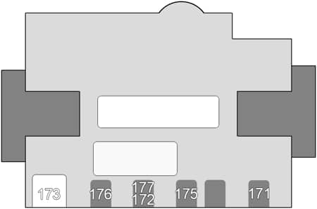
Fusible Link Block (Non-Replaceable)
| No. |
A |
Protected Component |
| 171 | 100 | →02.2007: Electric Fan |
| 100 | 03.2007→: Electric Fan Cut-Out Relay, Electric Fan (with Trailer Module) | |
| 172 | 100 | Rear Power Distribution Box (Luggage Compartment Fuse Box) |
| 173 | 250 | Junction Box (Passenger Compartment Fuse Box) |
| 176 | 80 | Petrol (except N55): Terminal 15 Power-Saving Relay |
| 80 | Diesel: Digital Diesel Electronics (DDE) Control Unit Relay | |
| 100 | N55: Integrated Supply Module | |
| 177 | 100 | →09.2008: Electric Auxiliary Heater |
| 80 | 10.2008→: Electric Auxiliary Heater |
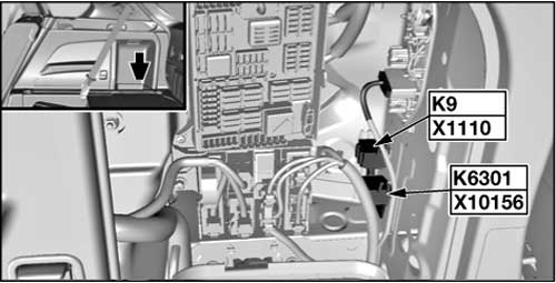
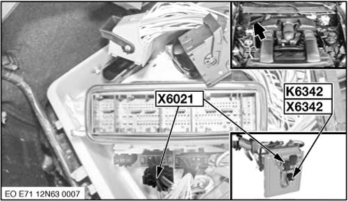
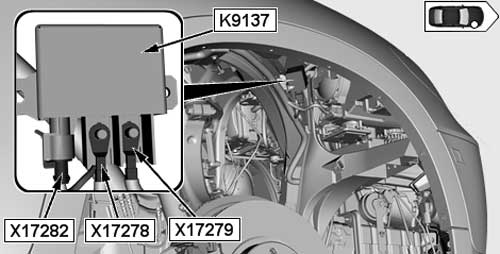
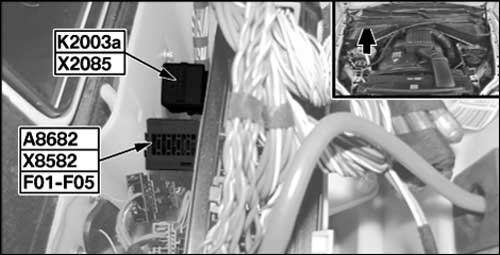
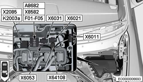
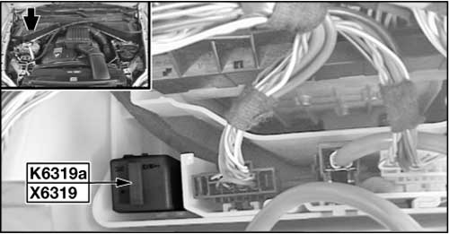
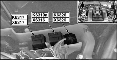
Relay
- SCR System Load Relay (K2085)
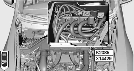
- Fuel Pump Relay (K6301)

- Terminal 15 Relief Relay (К9)
- Quantity Control Valves Relay (К6342) N63, S63 / N62

- Electric Fan Cutoff Relay (К9137)
- Digital Diesel Electronics (DDE) Control Unit Relay (K2003a): LHD / RHD
- N52: Valvetronic Relay (K6319a)
- N62: Valvetronic Relay (K6319a (No.1), К6317 (No.2))

WARNING: Terminal and harness assignments for individual connectors will vary depending on vehicle equipment level, model, and market.