Chrysler Concorde (1993 – 1997) – fuse box diagram
Year of production: 1993, 1994, 1995, 1996, 1997
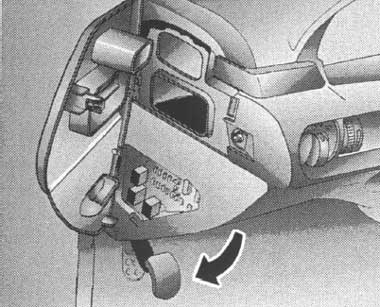
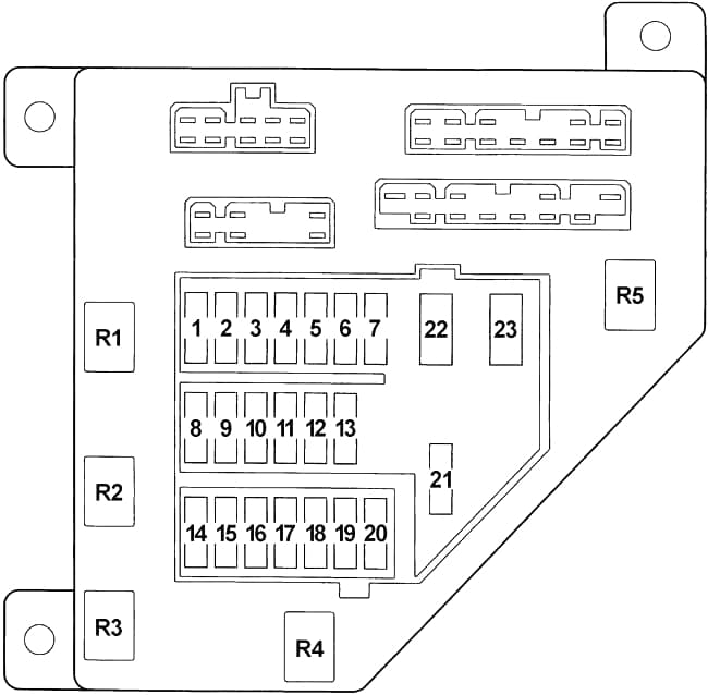
Passenger compartment fuse box
| № |
A |
Protected Component |
| 1 | 5 | Heated Power Mirrors |
| 2 | 10 | Radio |
| 3 | 10 | Right & Left Turn Signals |
| 4 | 20 | Stoplights |
| 5 | 5 | Headlight Delay Sense |
| 6 | 10 | Climate Control, Rear Window Defrost, Back-Up Lights, ABS Module, Daytime Running Lights, Speed Proportional Steering |
| 7 | 10 | Air Bag Module |
| 8 | 20 | Horns, Horn Relay, Cigarette Lighter, Radio Amplifier |
| 9 | 15 | Taillights, License & Parking Lights, Illumination Lights, Radio |
| 10 | 10 | Wiper Motor Relay, Washer Motor |
| 11 | 15 | Left High Beam Headlight |
| 12 | 15 | Right High Beam Headlight, High Beam Indicator |
| 13 | 10 | Body Controller, Door Lock Switches, Instrument Panel Connector, Radio Memory, Power Mirrors, Trunk Release, Remote Keyless Entry, Message Center, ATC Aspirator Motor, Lights: Rear Reading, Map, Glove Box, Key-In, Vanity Mirror, Underhood, Trunk, Door & Front Courtesy |
| 14 | 5 | Body Controller, Message Center, Speed Control Relay (’93-’95), Power Window Switch, Door Lock Switch Light, Power Mirrors, Overhead Console, Remote Keyless Entry, Sunroof Control Module |
| 15 | 15 | Left Low Beam |
| 16 | 15 | Right Low Beam, Foglights |
| 17 | 5 | Auto Trans Controller, Body Controller, Gear Selector Indicator |
| 18 | 10 | Engine Controller, Fuel Pump Relay, ASD Relay |
| 19 | 10 | Air Bag Module |
| 20 | 10 | Oxygen Sensor, Fan Relay, Purge Solenoid, EGR Solenoid, A/C Relay, Fan Relays, Manifold Solenoid |
| 21 | 25 | Blower Motor |
| 22 | 20 | Circuit Breaker: Power Window Motors, Power Window Switch Lights |
| 23 | 20 | Circuit Breaker: Power Door Lock Motors, Power Seats, Power Antenna, Sunroof Control Module |
| Relay | ||
| R1 | Door Unlock | |
| R2 | Door Lock | |
| R3 | Horn | |
| R4 | – | |
| R5 | Headlamp Delay | |
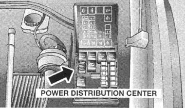
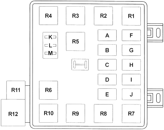
Engine compartment
| № |
A |
Protected Component |
| A | 20 | ’94-’97: Ignition Switch, Starter Relay, Fuel Pump Relay |
| 20 | ’93: Powertrain Control Module (PCM), Automatic Shut Down Relay, Transmission Relay, Transmission Control Module (TCM) | |
| B | 20 | ’94-’97: Powertrain Control Module (PCM), Automatic Shut Down Relay, Transmission Relay, Transmission Control Module (TCM) |
| 20 | ’93: Ignition Switch | |
| C | 40 | ’94-’97: ABS Pump Motor Relay |
| 30 | ’93: Intermmitent Wiper Relay | |
| D | 40 | High Speed Radiator Fan Relay, Low Speed Radiator Fan, A/C Compressor Clutch Relay |
| E | 30 | ’94-’97: Intermmitent Wiper Relay |
| 30 | ’93: Headlamp Switch, Headlamp Dimmer Switch, Headlamp Delay Relay, Fuse No.: “L”; Circuit Breaker: “23” | |
| F | 20 | ’94-’97: Fuse No.: “8”, “9” |
| 40 | ’93: ABS Motor Relay | |
| G | 20 | ’94-’97: Fuse No.: “4”, “13” |
| 40 | ’93: Ignition Switch | |
| H | 30 | ’94-’97: Headlamp Switch, Headlamp Dimmer Switch, Headlamp Delay Relay, Fuse No.: “L”; Circuit Breaker: “23” |
| 30 | ’93: ABS Main Relay, ABS Control Module | |
| I | 30 | ’94-’97: ABS Main Relay, ABS Control Module |
| 20 | ’93: Fuse No.: “8”, “9” | |
| J | 40 | ’94-’97: Ignition Switch |
| 20 | ’93: Fuse No.: “4”, “13” | |
| K | 20 | Combination Flasher (Hazard Warning Light) |
| L | 10 | Daytime Running Lamp Module |
| M | – | – |
| Relay | ||
| R1 | High Speed Radiator Fan | |
| R2 | Low Speed Radiator Fan | |
| R3 | A/C Compressor Clutch | |
| R4 | Automatic Shut Down | |
| R5 | Fuel Pump | |
| R6 | Intermmitent Wiper | |
| R7 | – | |
| R8 | Starter | |
| R9 | Transmission | |
| R10 | Wiper (High/Low Speed) | |
| R11 | ABS Main | |
| R12 | ABS Pump Motor | |
Fusible Link
- WHT (22 Ga) – Fuse No.: “K” (Combination Flasher)
- BRN (18 Ga) – A/C Heater Control (Manual A/C) / Automatic Temp Control Module (Auto A/C)
- BLK (12 Ga) – Alternator
WARNING: Terminal and harness assignments for individual connectors will vary depending on vehicle equipment level, model, and market.