Jeep Grand Cherokee WK2 (2011 – 2013) – fuse box diagram
Year of production: 2011, 2012, 2013
Fuse box
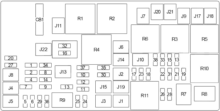
| No. | A | Description |
|---|---|---|
| J1 | 40 | Air Suspension |
| J2 | 30 | Power Liftgate Module |
| J3 | 30 | Trailer Tow |
| J4 | 25 | Driver Door Node |
| J5 | 25 | Passenger Door Node |
| J6 | 40 | ABS (Pump) |
| J7 | 30 | ABS (Valve) |
| J8 | 40 | Power Seats |
| J9 | 30 | E-Brake |
| J10 | 30 | Headlamp Wash Relay |
| J11 | 30 | Drive Train Control Module |
| J13 | 60 | Streaming Video Module, Video System 3 Module, Video System 2 Module, Display, DVD |
| J14 | 20 | Trailer Tow Lamps, Park Lamps |
| J15 | 30 | Rear Window Defroster |
| J17 | 40 | Starter Solenoid |
| J18 | 20 | Powertrain Control Module (PCM), Transmission Control Relay |
| J19 | 60 | Radiator Fan |
| J20 | 30 | Front Wiper |
| J21 | 20 | Front Washer, Rear Washer |
| J22 | 25 | Sunroof Module |
| 1 | 15 | Stop Lamp Switch, Center High-Mounted Stop Light (CHMSL) |
| 2 | 20 | Electronic Limit Slip Differential, Air Suspension |
| 3 | 20 | Liftgate Unlock, Daytime Running Light Relay |
| 4 | – | – |
| 5 | 25 | 115V AC Power Inverter |
| 6 | 20 | Power Outlet No.1, Rain Sensor |
| 7 | 20 | Power Outlet No.2 (Switchable) |
| 8 | 20 | Front Heated Seat, Heated Steering Wheel |
| 9 | 20 | Rear Heated Seat |
| 10 | 20 | Hands-Free Module, Universal Garage Door Opener, Vanity Lamp |
| 11 | 10 | Heating, Ventilation & Air Conditioning (Climate Control System) |
| 12 | 30 | Radio, Amplifier |
| 13 | 20 | Main #2 Instrument Cluster, Wireless Control Module, ITM, Siren, Multifunction Switch (Steering Control Module) |
| 14 | 20 | Back Up Camera |
| 15 | 20 | Power Seat Module, Adaptive Cruise Control, Audio Telematics, Daytime Running Lights Relay, Air Suspension Module, Instrument Cluster |
| 16 | 10 | Occupant Restraint Controller (ORC) |
| 17 | – | – |
| 18 | – | – |
| 19 | 25 | Auto Shut Down (ASD No.1 and No.2) |
| 20 | 15 | Instrument Cluster Interior Lighting Feed, Switch Steering Wheel, Switch Bank, Steering Control Module (Temperature/Compass Display) |
| 21 | 20 | Auto Shut Down (ASD No,3) |
| 22 | 10 | Right Horn |
| 23 | 10 | Left Horn |
| 24 | 25 | Rear Wiper |
| 25 | 20 | Fuel Pump Motor Output, Diesel Lift Pump |
| 26 | – | – |
| 27 | 10 | Ignition Switch, Wireless Control Module, Keyless Entry Module |
| 28 | 10 | Powertrain Control Module (PCM), Transmission Control Module (TCM) |
| 29 | 10 | Tire Pressure Monitoring System |
| 30 | 15 | Diagnostic Connector |
| 31 | – | – |
| 32 | 10 | Occupant Restraint Controller (ORC) |
| 33 | 10 | Powertrain Control Module (PCM), Transmission Control Module (TCM) |
| 34 | 10 | Park Assist Module, Climate Control System Module, IR Sensor, Compass Module |
| 35 | 15 | LH Rear Parklamps |
| 36 | 20 | Power Outlet No.3 |
| 37 | 10 | ABS, Electronic Stability Control, Stop Lamp Switch Sensor |
| 38 | 25 | Door & Liftgate Lock/Unlock Motors |
| Circuit Breaker | ||
| CB1 | 25 | Power Windows, Power Vent Window |
| Relay | ||
| R1 | Ignition (Run/Accessory) | |
| R2 | Ignition (Run) | |
| R3 | Starter | |
| R4 | Ignition (Run-Start) | |
| R5 | Powertrain Control Module (PCM)/Transmission Control Module (TCM) | |
| R6 | Trailer Tow Lamps/Park Lamps | |
| R7 | Diesel: Fuel Pump | |
| R8 | – | |
| R9 | Electrical Back Light (EBL) | |
| R10 | Automatic Shutdown | |
| R11 | Radiator Fan (Low Speed) | |
WARNING: Terminal and harness assignments for individual connectors will vary depending on vehicle equipment level, model, and market.