Lincoln Mark VIII (1996 – 1998) – fuse box diagram
Year of production: 1996, 1997, 1998, 1999
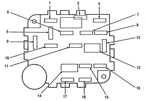
The instrument panel fuse box
| Fuse location | Fuse ampere rating | Description |
| 17 | 10 | Electric instrument panel |
| 18 | — | Not used |
| 19 | 10 | Steering column/ignition/lighting module |
| 20 | 10 | Message center. electronic instrument panel. electronic Automatic Temperature Control module |
| 21 | 10 | Anti-lock brake control module |
| 22 | — | Not used |
| 23 | — | Not used |
| 24 | — | Not used |
| 25 | 10 | Steering column/ignition/lighting module |
| 26 | 15 | Steering column/ignition/lighting module |
| 27 | — | Not used |
| 28 | 10 | I/P warning indicator display, Air suspension/electronically variable orifice power steering module, rear windows defrost module, steering wheel position sensor, transmission control switch |
| 29 | — | Not used |
| 30 | 10 | Heated mirrors |
| 31 | 10 | Steering column/ignition/lighting module |
| 32 | 15 | Stop lamp switch |
| 33 | — | Not used |
| 34 | 15 | Heated seats, backup lamps, speed control, daytime running lamps, powertrain control module, electronic automatic temparature control module, day/night mirror |
| 35 | 10 | Driver’s power and heated seats |
| 36 | — | Not used |
| 37 | — | Not used |
| 38 | 10 | data link connector |
| 39 | — | Not used |
| 40 | — | Not used |
| 41 | 10 | Keyless entry, power door locks, power mirror switch, memory/recall switch, driver’s door module |
The high current fuses
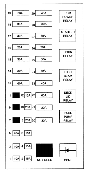
| Fuse location | Fuse ampere rating | Description |
| 1 | 10 MINI | Powertrain control module |
| 2 | 15 MINI | High beam relay, daytime running lamps module |
| 3 | 10 MINI | Thermactor pump motor |
| 4 | 15 MINI | Air suspension, electronically variable orifce powe steering |
| 5 | 30 MINI | Trunk Lid Relay |
| 6 | 10 MINI | Air bag |
| 7 | — | The high current fuses |
| 8 | 20 MINI | Horn relay |
| 9 | — | The high current fuses |
| 10 | 20 MINI | Radio aplifer, CD changer |
| 11 | — | The high current fuses |
| 12 | 15 MINI | Steering column/ignition/lighting module |
| 13 | 60 MAXI | Air suspension |
| 14 | 30 MAXI | Delayed accessory power relay #1 |
| 15 | 30 MAXI | Powertrain control module, PCM power relay, engine compartment fuse I |
| 16 | 20 MAXI | Fuel pump relay, fuel pump module |
| 17 | 30 MAXI | Electric air management, engine compaartment fuse 3 |
| 18 | 30 MAXI | Passeneger seat module, passenger lumbar, I/P fuse 12 |
| 19 | 30 MAXI | Driver seat module, driver lumbar, I/P fuse 35 |
| 20 | 30 MAXI | Anti-lock brake control module |
| 21 | 20 MAXI | Anti-lock brake control module, EVAC/fill connector |
| 22 | 60 MAXI | I/P fuses 1,7,13,19,25,31 |
| 23 | 40 MAXI | Variable load control module |
| 24 | 40 MAXI | Rear window defrost control, I/P fuse 30 |
| 25 | 60 MAXI | I/P fuses 2,14,20,26,32,38, engine compartment fuse 5 |
| 26 | 20 MAXI | Ignition switch, I/P fuses (5,9,11,15,17,21) |
| 27 | 30 MAXI | Starter moptor solenoid, ignition switch, I/P fuse 6,28,34 |
| 28 | 30 MAXI | Delayed accessory power #2, I/P fuse 41 |
| 29 | 40 MAXI | Blower motor relay |
WARNING: Terminal and harness assignments for individual connectors will vary depending on vehicle equipment level, model, and market.