Land Rover Discover II (1998 – 2005) – fuse box diagram
Year of production: 1998, 1999, 2000, 2001, 2002, 2003, 2004, 2005
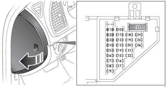
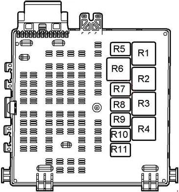
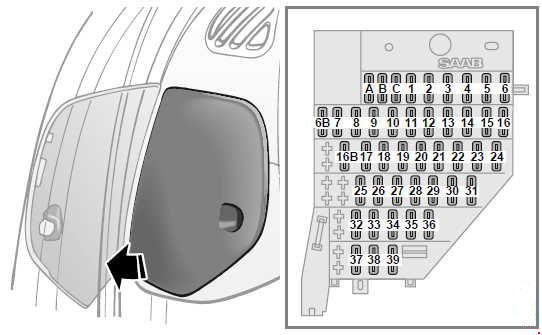
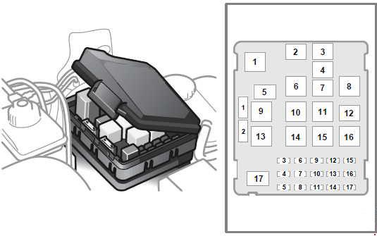
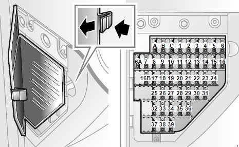
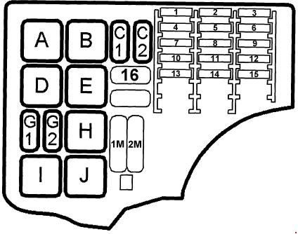
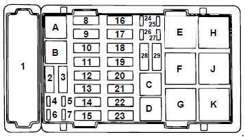
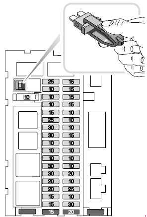
Main fuse box
The main fuse box is fitted below and to one side of the steering column;
| № |
A |
Circuit protected |
| 1 | 25 | Central door locking |
| 2 | 10 | Fuel flap release |
| 3 | 10 | Instrument pack Switch illumination |
| 4 | 10 | Fog guard lights – rear |
| 5 | 10 | Headlight high beam – LH |
| 6 | 25 | Air conditioning blower – rear |
| 7 | 30 | Heater blower – front |
| 8 | 30 | Heated rear window Heated mirrors |
| 9 | 10 | Headlight normal beam – LH |
| 10 | 10 | Headlight normal beam – RH |
| 11 | 10 | Side & tail lights – LH Number plate light Switch illumination Trailer socket |
| 12 | 30 | Sunroof |
| 13 | 30 | Electric windows – rear |
| 14 | 20 | Ignition coils |
| 15 | 20 | Cigar lighter Interior lights Seat heaters Vanity mirror illumination |
| 16 | 15 | Clock Radio Park distance control Rear head phones |
| 17 | 15 | Radio amplifier Speakers |
| 18 | 15 | Wiper motor – rear |
| 19 | 15 | Wiper motor – front Screen washer – front |
| 20 | 15 | Interior lights Clock/radio memory Engine remobilisation Compact disc player Key i/lock Diagnostics |
| 21 | 15 | Transfer box Alarm audible warning Shift i/lock |
| 22 | 10 | Headlight high beam – RH |
| 23 | 10 | Starter motor |
| 24 | 10 | Alternator Automatic transmission Engine management |
| 25 | 15 | Brake lights Reverse lights |
| 26 | 10 | Auxiliary circuits relays |
| 27 | 10 | Instruments Hill descent control |
| 28 | 10 | Self levelling suspension Anti-lock braking |
| 29 | 10 | Active cornering enhancement (ACE) |
| 30 | 20 | Cruise control Electric mirrors Screen washer – rear |
| 31 | 10 | Air conditioning blower – front |
| 32 | 25 | Accessory socke |
| 33 | 10 | Side & tail lights – RH Radio Trailer socket Switch illumination |
| 34 | 30 | Electric windows – front |
| 35 | 10 | Airbag SRS |
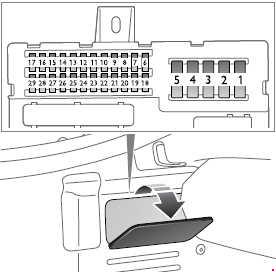
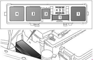
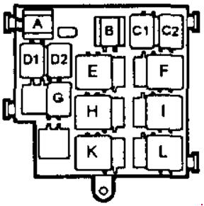
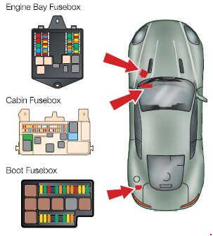
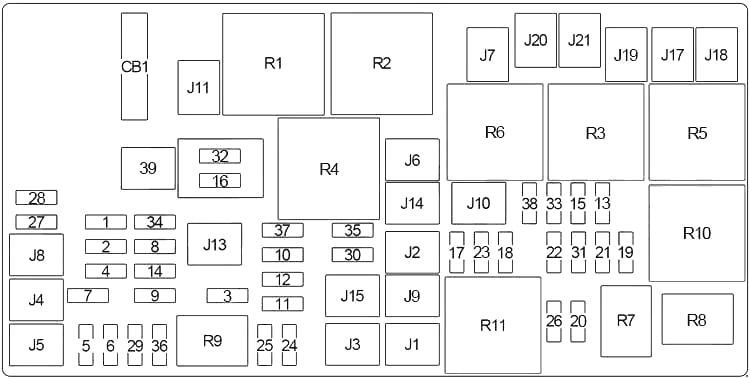
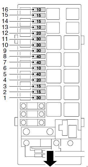
Engine Compartment Fuse Box
A second fuse box is located on the right side of the engine compartment adjacent to the coolant reservoir.
| № |
A |
Circuit protected |
| 1 | 30 | Fuel injectors |
| 2 | 15 | Engine management system |
| 3 | 15 | Front fog lights |
| 4 | 20 | Headlight washers |
| 5 | 40 | Cooling fans |
| 6 | 10 | Air conditioning |
| 7 | 40 | Heated front screen – LH |
| 8 | 40 | Heated front screen – RH |
| 9 | 30 | Trailer lights |
| 10 | 30 | Fuel pump |
| 11 | 30 | ABS valve |
| 12 | 20 | Automatic gearbox |
| 13 | 10 | Body Control Unit (BCU) |
| 14 | 15 | Direction indicators Hazard lights |
| 15 | 15 | Active cornering enhancement (ACE) |
| 16 | 10 | Horn |
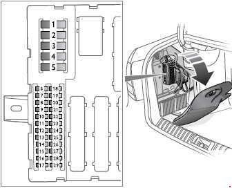
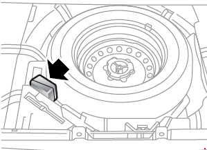
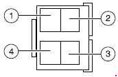
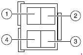
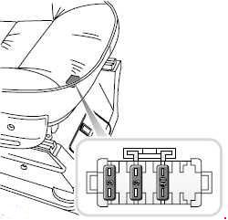
Underseat fuses
Two identical small fuse blocks are situated one beneath each front seat.
| № |
A |
Circuit protected |
| 1 | 40 | Seat electrics |
| 2 | 3 | Lumbar support – pump |
| 3 | 3 | Lumbar support – solenoid |
WARNING: Terminal and harness assignments for individual connectors will vary depending on vehicle equipment level, model, and market.