ABS control unit and sensor – ASR sensor – DSC sensor – Brake lamp switch
43
20
Windscreen wiper motor (ignition switch +)
47
20
Driver’s electric window motor
48
20
Passenger’s electric window motor
49
5
Parking sensors control unit – Audio system – Steering mounted controls – Centre and side switch panels -Auxiliary switch panel – Battery cut-off control unit (ignition switch +)
50
7.5
Airbags and pre-tensioners control unit
51
5
Tachograph – Power steering control unit – Air conditioning – Reversing lamps – Water in Diesel sensor -Air flow sensor (ignition switch +)
+15 services (sound system, cellular telephone, dashboard control lighting, electrical mirrors, trailer, heated seat control lighting) – Safet belt buzzer muting relay
50
7.5
Air bag
51
7.5
Dashboard instrument lights – Number plate light
52
15
Rear window wiper
53
10
Hazard lights – Direction indicators – Instrument panel and warning lights (battery powered)
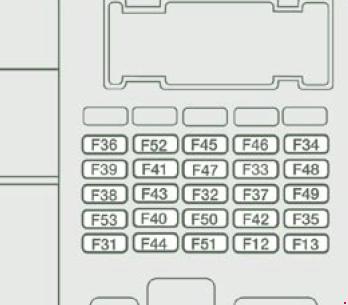
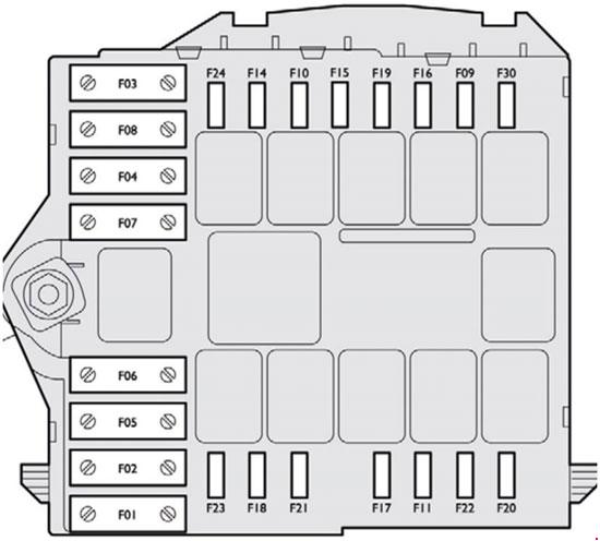
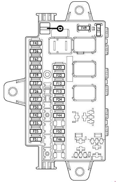
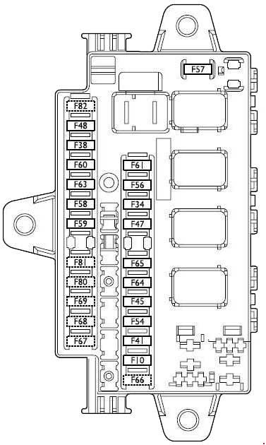
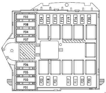
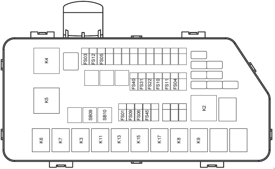
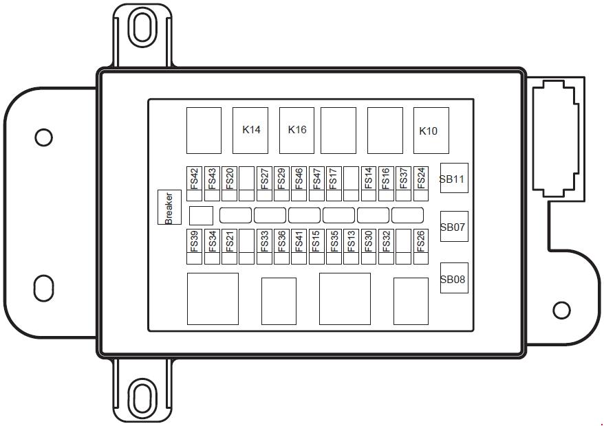
Fuses in the engine compartment
Fiat Doblo – fuse box diagram – engine compartment
No.
A
Function
1
70
Dashboard control unit power: standard functions
2
40
Dashboard control unit power: optional functions
3
20
Ignition switch
4
40
ABS power (pump)
5
30
ABS power (valve)
6
30
One-speed radiator fan
6
30
Radiator fan first speed (versions with manual climate control system)
6
40
Radiator fan first speed (1.3 -1.9 Multijet versions)
7
60
Radiator fan second speed (1.4 – 1.6 versions with manual climate control system)
7
40
Radiator fan second speed (1.3 -1.9 Multijet versions)
8
30
Passenger compartment fan
9
–
Not used
10
15
Horn
11
15
Engine control system secondary loads – Glow plug control unit – Petrol fume recirculation solenoid valve – Tachometer generator – Lambda sensors (oxygen sensors)
14
10
Right-hand main beam
15
10
Left-hand main beam
16
7.5
Engine control unit (ignition switch powered) – Engine control system relay
17
10
Engine control unit (power)
18
7.5
Engine control unit (+battery) – Engine cooling system relay
19
7.5
Manual climate control compressor
20
–
Not used
21
15
Fuel pump
22
20
Ignition coils – Injectors – Fuel pump
23
–
Not used
24
–
Not used
30
15
Front fog lights
WARNING: Terminal and harness assignments for individual connectors will vary depending on vehicle equipment level, model, and market.
Radiator fan low-speed resistor (2.0 with climate control system)
Engine control unit (2.0 with climate control system)
Engine cooling fan (2.0 with climate control system)
Engine control unit (2.0 with climate control system)
6
40
Engine cooling fan 1st speed
Engine control unit 1st speed
7
40
Engine cooling fan (2.0 with climate control system)
Engine control unit (2.0 with climate control system)
7
40/60
Engine cooling fan 2nd speed
Engine control unit 2nd speed
Radiator fan 2nd speed remote switch coil (climate control)
8
30
Windscreen wiper motor – Windscreen washer pump
9
15
Front fog lights
10
15
Horn – Steering column stalk control
11
10
E.I. secondary services – Engine control unit
14
10
Right-hand dipped beam headlight
15
10
Left-hand dipped beam headlight
16
7.5
E.I. system – Fiat code
17
5
E.I. primary services – Engine control unit
18
7.5
Fiat code – Engine control unit
19
7.5
Compressor
20
30
PTC
21
15
Fuel pump
22
20
E.I. primary services
23
10
Automatic gearbox control unit
24
15
Automatic gearbox control unit
30
15
Main beam headlights
WARNING: Terminal and harness assignments for individual connectors will vary depending on vehicle equipment level, model, and market.