Suzuki Celerio (2014 – present) – fuse box diagram
Year of production: 2014, 2015, 2016, 2017, 2018
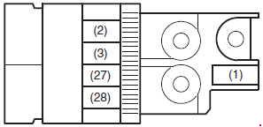
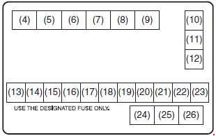
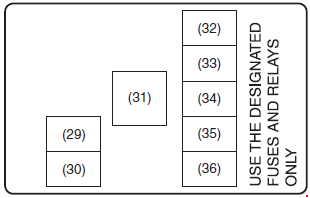
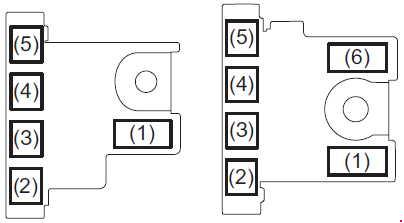
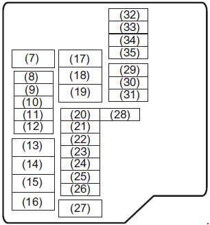
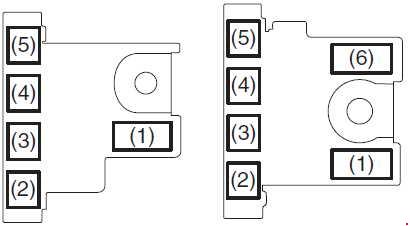
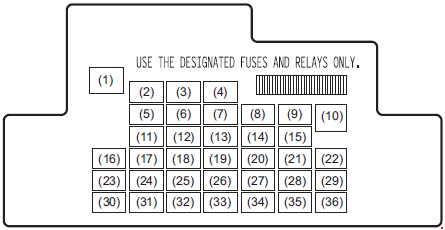
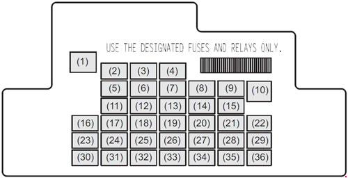
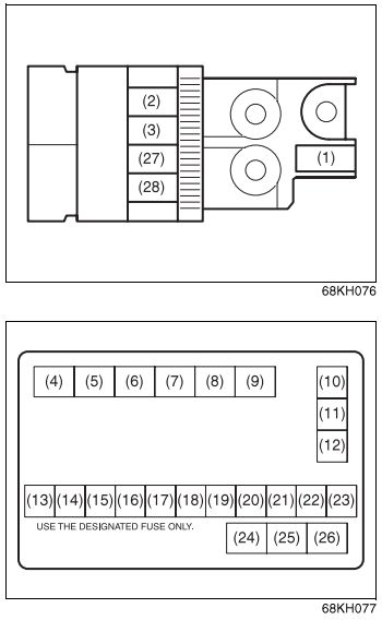
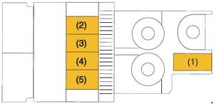
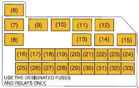
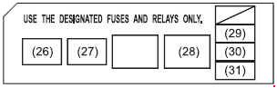
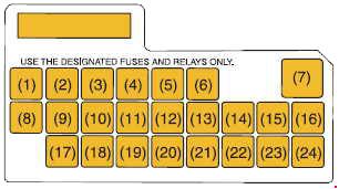
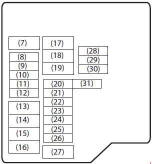
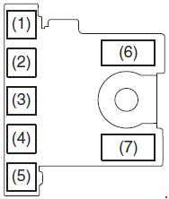
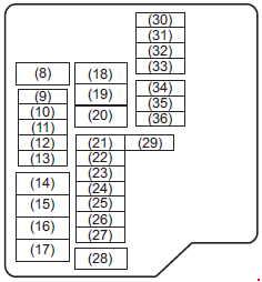
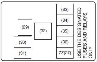
Fuse box in the engine compartment


| No. |
A |
Function/component |
| 1 | 80 | FL1 (PETROL) |
| 120 | FL1 (DIESEL) | |
| 2 | 50 | FL5 (PETROL) |
| 40 | FL5 (DIESEL) | |
| 3 | 50 | FL4 |
| 10 | 40 | ABS motor |
| 11 | 40 | T/M pump (PETROL) |
| 40 | IGN2 (DIESEL) | |
| 12 | 40 | Power steering |
| 13 | 20 | Front fog light |
| 14 | 7.5 | T/M 2 (PETROL), CNG Valve (Compressed Natural Gas) |
| 25 | F/P (DIESEL) | |
| 15 | 30 | Ignition switch |
| 16 | 10 | Air compressor |
| 17 | 15 | FI (PETROL) |
| 30 | FI (DIESEL) | |
| 18 | 10 | T/M (PETROL) |
| 10 | EPI (DIESEL) | |
| 19 | 15 | Headlight (Right) |
| 20 | 25 | ABS control module |
| 21 | 15 | Headlight (Left) |
| 22 | 30 | Starting motor |
| 23 | 30 | Radiator fan |
| 27 | 80 | FL3 (PETROL) |
| 100 | FL3 (DIESEL) | |
| 28 | 80 | FL2 (PETROL) |
| 100 | FL2 (DIESEL) | |
| 29 | 20 | Glow plug |
| 30 | 20 | Glow plug 2 |
| 32 | – | Not used |
| 33 | 15 | FI2 |
| 34 | 20 | INJ DRV |
| 35 | – | Not used |
| 36 | – | Not used |
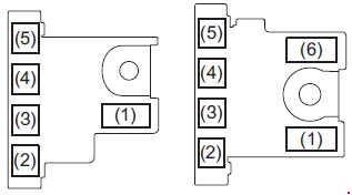
| Relay |
||
| 4 | Front fog light relay | |
| 5 | Glow plug relay | |
| 6 | CNG Valve relay (Compressed Natural Gas) | |
| 7 | Air compressor relay | |
| 8 | Back up relay | |
| 9 | F/P relay | |
| 24 | FI main relay (PETROL) | |
| Glow plug 2 relay (DIESEL) | ||
| 25 | Starting motor relay | |
| 26 | Radiator fan relay | |
| 31 | FI main relay | |
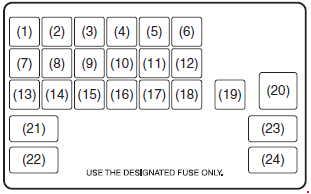
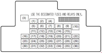
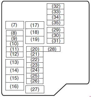
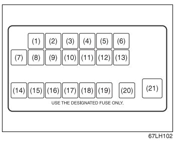
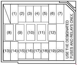
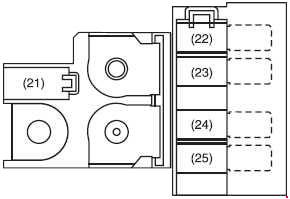
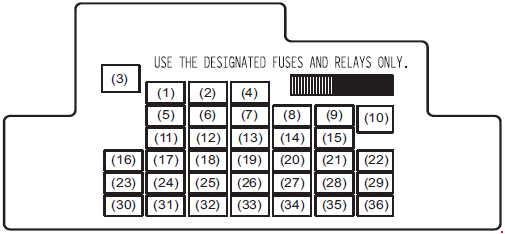
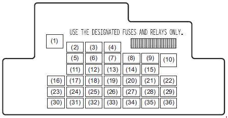
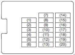
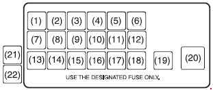
Fuse box under the dashboard

| No. |
A |
Function/component |
| 1 | 10 | Stop light |
| 2 | 30 | Blower motor |
| 3 | 10 | STSIG |
| 4 | 15 | Accessory |
| 5 | 10 | Rear fog light |
| 6 | 10 | Tail light |
| 7 | 10 | Back-up light |
| 8 | 10 | ABS |
| 9 | 10 | Meter |
| 10 | 15 | Ignition coil |
| 11 | 20 | Wiper/Washer |
| 12 | 10 | IG2 SIG |
| 13 | 10 | IG1 SIG |
| 14 | 10 | Air bag |
| 15 | 20 | Power window timer |
| 16 | 20 | Door lock |
| 17 | 15 | Horn/Hazard |
| 18 | 20 | Rear defogger |
| 19 | 15 | Dome |
| 20 | 30 | Power window |
| 21 | 7.5 | ACC 2 |
| 21 | CNG (Compressed Natural Gas) | |
| 22 | 15 | Radio 2 |
| 23 | – | ACC 2 (Compressed Natural Gas) |
| 24 | – | Not used |
WARNING: Terminal and harness assignments for individual connectors will vary depending on vehicle equipment level, model, and market.