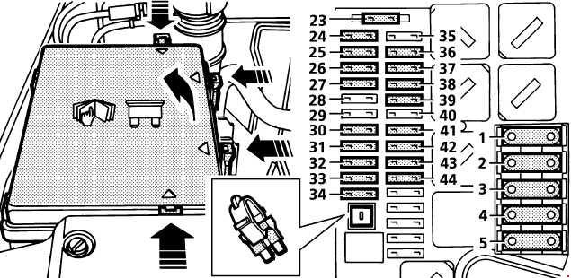
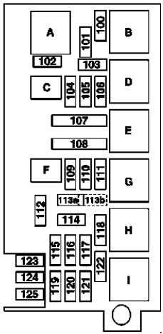
No.
|
Description
|
A
|
| 20 |
Up to 2008: Roof antenna module
As of 2009: Interference suppression filter for radio antenna
As of 2009: Microphone array control unit (Japanese version) |
5 |
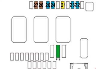
| 21 |
RCP [HBF] control unit |
5 |
| 22 |
PTS control unit
STH radio remote control receiver |
5 |
| 23 |
DVD player
Rear audio control unit
Portable CTEL separation point (Japanese version)
E-net compensator
Bluetooth module
Universal Portable CTEL Interface (UPCI [UHI]) control unit (Japanese version) |
10 |
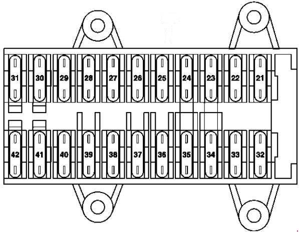
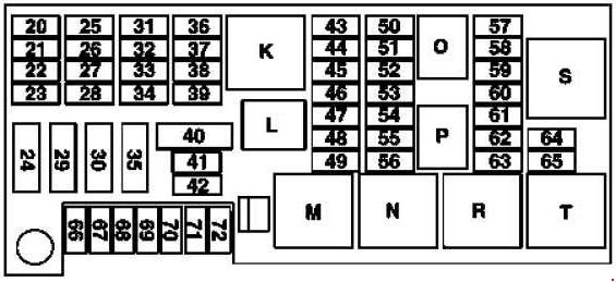
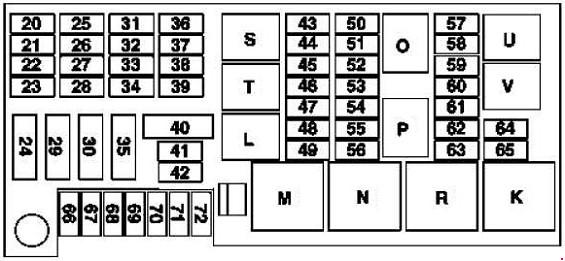
| 24 |
Right front reversible emergency tensioning retractor |
40 |
| 25 |
COMAND operating, display and control unit |
15 |
| 26 |
Right front door control unit |
25 |
| 27 |
Passenger-side front seat adjustment control unit with memory
Front passenger seat adjustment comfort relay |
30 |
| 28 |
Driver-side front seat adjustment control unit, with memory
Driver seat adjustment comfort relay |
30 |
| 29 |
Left front reversible emergency tensioning retractor |
40 |
| 30 |
As of 2009: Folding rear bench seat control unit
Valid for engine 156:
Left fuel pump control unit
Right fuel pump control unit
Valid for model 164.195 (ML 450 Hybrid): Fuel pump control unit circuit 30 connector sleeve |
40 |
| 31 |
HS [SIH], seat ventilation and steering wheel heater control unit |
10 |
| 32 |
AIRmatic control unit |
15 |
| 33 |
KEYLESS-GO control unit |
25 |
| 34 |
Left front door control unit |
25 |
| 35 |
Amplifier for sound system
As of 2009: Subwoofer amplifier |
30 |
| 36 |
Emergency call system control unit |
10 |
| 37 |
Backup camera power supply module (Japanese version)
Backup camera control unit (Japanese version) |
5 |
| 38 |
Digital TV tuner
Up to 2008: Audio gateway control unit (Japanese version)
As of 2009: TV combination tuner (analog/digital) (Japanese version)
Valid for model 164.195 (ML 450 Hybrid): High voltage battery module |
10 |
| 39 |
Tire pressure monitor [RDK] control unit
Up to 2008: SDAR control unit (USA version)
As of 2009: High definition tuner control unit
As of 2009: Digital Audio Broadcasting control unit
As of 2009: External navigation separation point (South Korea version) |
7.5 |
| 40 |
Up to 2008: Rear-end door closing control unit |
40 |
| As of 2009: Rear-end door closing control unit |
30 |
| 41 |
Overhead control panel control unit |
25 |
| 42 |
Up to 2008: SR motor
As of 2009: Overhead control panel control unit |
25 |
| 43 |
As of 2009; Valid for engine 272, 273: Fuel pump control unit
Up to 31.05.2006: Tailgate wiper motor
As of 01.06.2006: Not assigned |
20 |
| 44 |
Up to 31.05.2006: Left 2nd seat row socket
Up to 31.05.2006: Right 2nd seat row socket
As of 01.06.2006: Not assigned
As of 2009: Front interior socket (USA)
As of 2009: 115V socket |
20 |
| 45 |
Cargo area connector box
Up to 2008: Front interior socket
As of 2009: Right 2nd seat row socket |
20 |
| 46 |
Front cigar lighter with ashtray illumination |
15 |
| 47 |
Valid for model 164.195 (ML 450 Hybrid): High voltage battery coolant pump
As of 2009: Left front illuminated door sill molding
As of 2009: Right front illuminated door sill molding |
10 |
| 48 |
As of 2009: Rear axle differential lock control unit
As of 2009; Valid for engine 642.820: AdBlue® supply relay
As of 1.7.09; Valid for model 164.195 or model 164.1 with engine 272 or model 164.8 with engine 642 or 273: Pyrotechnical separator |
5 |
| 49 |
Heated rear window |
30 |
| 50 |
Up to 31.05.2006: Tailgate wiper motor |
10 |
| As of 01.06.2006: Tailgate wiper motor |
15 |
| 51 |
Activated charcoal canister shutoff valve |
5 |
| 52 |
Up to 31.5.09: Left front reversible emergency tensioning retractor
Up to 31.5.09: Right front reversible emergency tensioning retractor
As of 2009: Rear axle differential lock control unit |
5 |
| 53 |
AIRmatic control unit
Valid for engine 156:
Left fuel pump control unit
Right fuel pump control unit
Valid for engine 272, 273: Fuel pump control unit
As of 2009: Transfer case control unit |
5 |
| 54 |
Headlamp range adjustment control unit
Front SAM control unit |
5 |
| 55 |
Instrument cluster
Rotary light switch |
7.5 |
| 56 |
Up to 31.05.2006: Data link connector
Valid for engine 642.820: AdBlue® control unit
Valid for model 164.195: Fuel pump control unit |
5 |
| 57 |
Up to 2008: Fuel pump with fuel gauge sensor
Valid without engine 156: Fuel pump |
20 |
| 58 |
Datalink connector
Central gateway control unit |
7.5 |
| 59 |
As of 2009: Driver NECK-PRO head restraint solenoid
As of 2009: Front passenger NECK-PRO head restraint solenoid |
7.5 |
| 60 |
Glove compartment illumination with switch
Engine compartment fuse and relay box
Rear SAM control unit
Cell phone separation point
VICS+ETC voltage supply separation point (Japan version)
Multicontour seat pneumatic pump (as of 2009)
External navigation separation point (South Korea)
Electrical connection, Blind-Spot-Monitoring interior rear bumper (as of 1.8.10)
Emergency call system control unit (USA) |
5 |
| 61 |
Up to 2008:
Restraint systems control unit
Right front seat contacting strip |
10 |
As of 2009:
Restraint systems control unit
Right front seat contacting strip |
7.5 |
| 62 |
Front passenger seat adjustment switch |
30 |
| 63 |
Driver lumbar support regulator control unit
Front passenger lumbar support regulator control unit
Driver seat adjustment switch |
30 |
| 64 |
Spare |
– |
| 65 |
Spare |
– |
| 66 |
As of 2009: Multicontour seat pneumatic pump |
30 |
| 67 |
Rear air conditioning blower motor |
25 |
| 68 |
Up to 2008: Left 2nd row seat heated cushion
Up to 2008: Right 2nd row seat heated cushion
As of 2009: HS [SIH], seat ventilation and steering wheel heater control unit |
25 |
| 69 |
As of 2009: Rear axle differential lock control unit |
30 |
| 70 |
Trailer hitch socket (13-pin) (as of 2009)
Trailer hitch socket (7-pin) |
20 |
| Trailer hitch socket (13-pin) (up to 2008) |
15 |
| 71 |
Electric brake control separation point |
30 |
| 72 |
Trailer hitch socket (13-pin) |
15 |
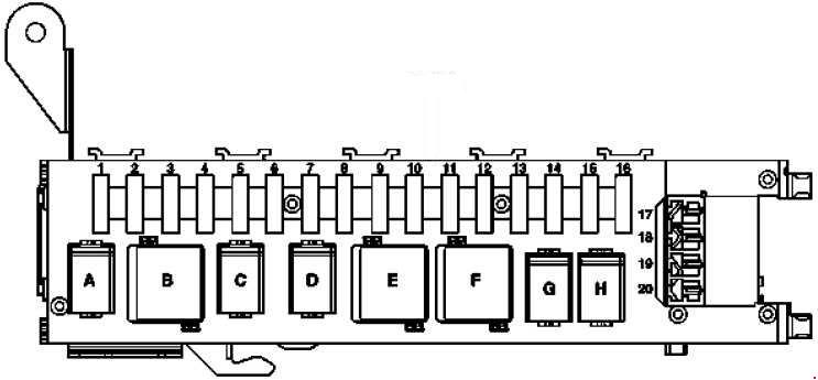
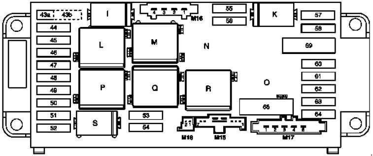
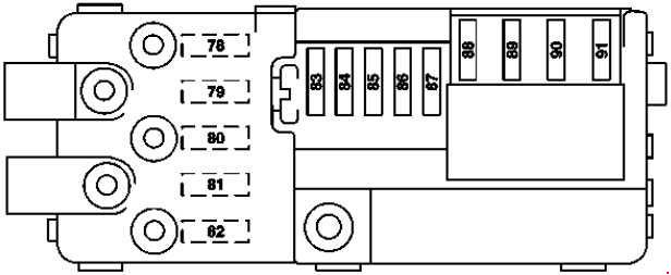
| Relay |
| K |
Up to 31.05.2006: Terminal 15R power outlet relay, with power-down
As of 01.06.2006: Circuit 15R seat adjustment
As of 2009: Relay, circuit 15R sockets (with K power-down) (power supply of electric seat adjustment) |
| L |
Terminal 30X |
| M |
Heated rear window relay |
| N |
Circuit 15 relay / terminal 87FW |
| O |
Fuel pump relay |
| P |
Rear wiper relay |
| R |
Circuit R relay115R |
| S |
Reserve 1 (changer) (power supply for front socket) |
| T |
As of 01.06.2006Circuit 30, socket for 2nd seat row and load compartment
As of 2009: Reserve 2 (normally open contact) (power supply for center and rear sockets) |
| U |
As of 01.06.2006Circuit 30, trailer |
| V |
As of 01.06.2006 – |