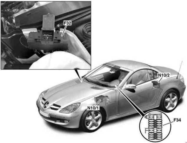
Mercedes-Benz SLK (R170; 1995 – 2004) – fuse box diagram
Year of production: 1995, 1996, 1997, 1998, 1999, 2000, 2001, 2002, 2003, 2004
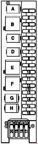
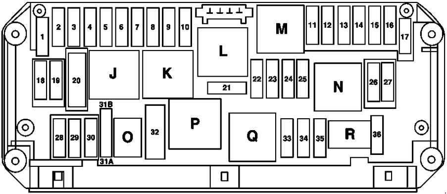
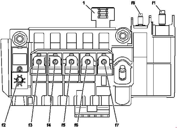
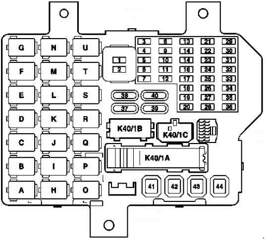
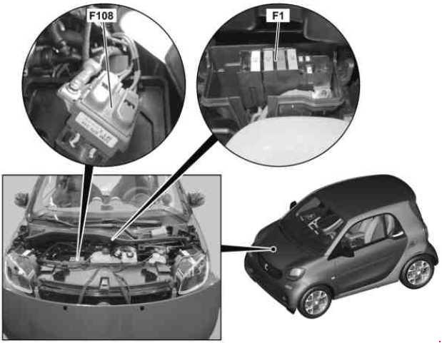
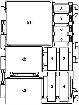
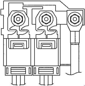
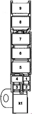
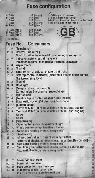
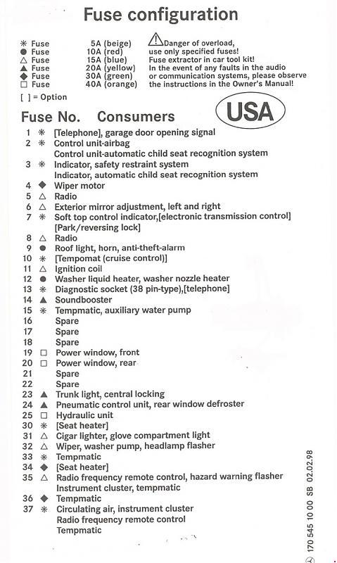
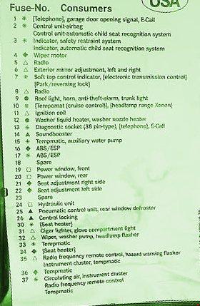
Fuse box
| No. | Fused function | A |
| 1 | Asra: Turn signal lamps Trailer turn signal lamps |
7.5 |
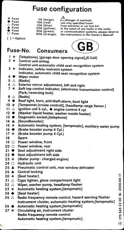
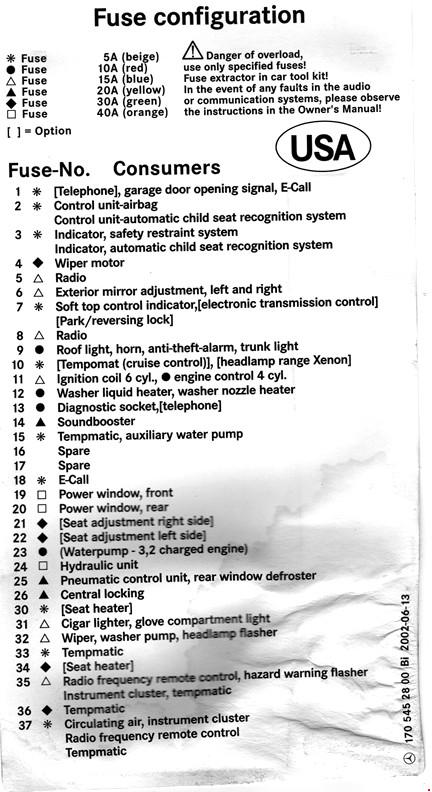
| 170 545 (01, 10, 20, 22, 28) 00: Telephone Garage door opening signal (170 545 (10, 20, 22, 28) 00) E-Call (170 545 (20, 22, 28) 00) |
5 | |
| 2 | Asra: Fanfare horn Automatic heater: (Circulated air valve Automatic heater) Daytime running lamp control module |
15 |
| Asra: Fanfare horn Air conditioning (Tempmatic): (Electric suction-type fan control module, Recirculated air valve) Air conditioning (Automatic): (Electric suction-type fan control module) Daytime running lamp control module |
20 | |
| 170 545 (01, 10, 20, 22, 28) 00: Control unit-airbag Control unit-automatic child seat recognition system |
5 | |
| 3 | Asra: Instrument cluster Exterior lamp failure monitoring module Stop lamp switch (Stop lamps, Trailer stop lamps, Center high-mounted stop lamp, Traction system control module) Heated windshield washer nozzle (Left, Right) Heated washer nozzle hose (Left, Right) |
15 |
| 170 545 (01, 10, 20, 22, 28) 00: Indicator, safety restraint system Indicator, automatic child seat recognition system |
5 | |
| 4 | Asra: Right low beam headlamp | 7.5 |
| Asra: ATA low beam (USA, CH) | 15 | |
| 170 545 (01, 10, 20, 22, 28) 00: Wiper motor | 30 | |
| 5 | Asra: Left low beam headlamp | 7.5 |
| 170 545 (01, 10, 20, 22, 28) 00: Radio | 15 | |
| 6 | Asra: Right high beam headlamp | 7.5 |
| 170 545 (01, 10, 20, 22, 28) 00: Exterior mirror adjustment, left and right | 15 | |
| 7 | Asra: Left high beam headlamp High beam headlamp indicator |
7.5 |
| 170 545 (01, 10, 20, 22, 28) 00: Soft top control indicator Electronic transmission control Park/reversing lock |
5 | |
| 8 | Asra: Left fog lamp Right fog lamp |
10 |
| 170 545 (01, 10, 20, 22, 28) 00: Radio | 15 | |
| 9 | Asra: Blower regulator Air conditioning (Automatic)/Air conditioning (Tempmatic) |
30 |
| 170 545 (01, 10, 20, 22, 28) 00: Roof light Horn (170 545 (10, 20, 22, 28) 00) Anti-theft-alarm (170 545 (10, 20, 22, 28) 00) Boot light (170 545 (20, 22, 28) 00) |
10 | |
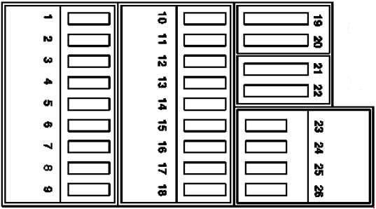
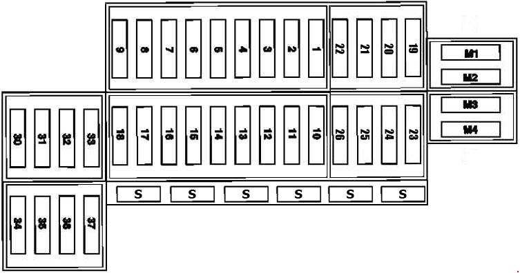
| 10 | Tempomat (cruise control) Crash shut-off relay (Asra, 170 545 01 00; SLK 200 Kompressor (170.445), SLK 230 Kompressor (170.447)) Headlamp range Xenon (170 545 (20, 22, 28) 00) |
5 |
| 11 | Ignition coils | 15 |
| Engine control | 10 | |
| 12 | Heated windshield washer system thermoswitch (Washer nozzles, Hose heater) | 10 |
| 13 | Asra, 170 545 (01, 10, 20) 00: Diagnostic socket Telephone E-Call (170 545 (20, ??) 00) |
5 |
| 170 545 (22, 28) 00: Diagnostic socket Telephone |
10 | |
| 14 | Asra, 170, 545, 01 00: Sound system (Left/right audio power amplifier) | 25 |
| 170 545 (10, 20, 22, 28) 00: Soundbooster | 20 | |
| 15 | Asra, 170 545 01 00: HFM-SFI engine control module (SLK 200 (170.435; 10.95 – 04.00) | 15 |
| 170 545 (10, 20, 22, 28) 00: Automatic heating system Tempmatic Auxiliary water pump |
5 | |
| 16 | Asra, 170 545 01 00: HFM-SFI engine control module (SLK 200 (170.435; 10.95 – 04.00) | 10 |
| 170 545 (20, 22) 00: ABS/ESP | 30 | |
| 17 | 170 545 (20, 22) 00: ABS/ESP | 5 |
| 18 | 170 545 28 00: E-Call | 5 |
| 19 | 170 545 (10, 20, 22, 28) 00: Power window, front | 40 |
| 20 | 170 545 (10, 20, 22, 28) 00: Power window, rear | 40 |
| 21 | 170 545 (20, 22, 28) 00: Seat adjustment right side | 30 |
| 22 | 170 545 (20, 22, 28) 00: Seat adjustment left side | 30 |
| 23 | 170 545 22 00: Water pump – charged engine | 5 |
| 170 545 28 00: Water pump – 3,2 charged engine | 10 | |
| 170 545 10 00: Central locking Boot light |
20 | |
| 24 | 170 545 (20, 22, 28) 00: Hydraulic unit | 40 |
| 170 545 10 00: Pneumatic control unit, rear window defroster | 20 | |
| 25 | 170 545 (20, 22, 28) 00: Pneumatic control unit, rear window defroster | 20 |
| 170 545 10 00: Hydraulic unit | 40 | |
| 26 | 170 545 (20, 22, 28) 00: Central locking | 20 |
| 30 | Seat heater | 5 |
| 31 | Front cigar lighter with ashtray illumination Glove compartment lamp |
15 |
| 32 | Combination switch (Wiper motor, Washer pump, Headlamp flasher) | 15 |
| 33 | Heater pushbutton control module | 5 |
| 34 | Asra, 170 545 01 00: Seat heater | 25 |
| 170 545 (10, 20, 22, 28) 00: Seat heater | 30 | |
| 35 | Closing confirmation relay Instrument cluster (Light warning buzzer) Stationary heater/heater booster unit Radio frequency remote control Hazard warning flasher |
15 |
| 36 | A/C system blower unit Automatic heating system Tempmatic |
30 |
| 37 | Diagnosis (OBD II) Radio frequency remote control Instrument cluster Automatic heater (HEAT): Heater pushbutton control module (HEAT) A/C control module (Tempmatic A/C) Fresh/recirculated air flap switchover valve |
5 |
| M1 | Asra, 170 545 01 00: Front power windows | 40 |
| M2 | Asra, 170 545 01 00: Rear power windows | 40 |
| M3 | Asra, 170 545 01 00: Fuse box in trunk | 80 |
| M4 | Asra, 170 545 01 00: Booster heater control module (SLK 200 Kompressor (170.445), SLK 230 Kompressor (170.447), left-hand steering LHS) | 40 |
| 170 545 01 00: Suction-type fan (tempmatic) (on RHD models in control unit box) | 50 |
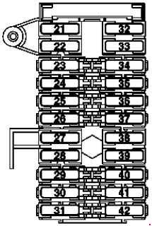
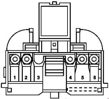
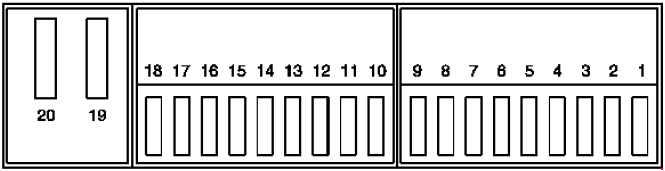
Fuse box on light module (left-hand steering)
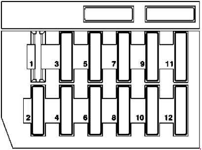
| No. | Fused function | A |
| 1 | Not used | – |
| 2 | Stop lamp switch Cruise control |
15 |
| 3 | Right high beam High beam indicator lamp |
7.5 |
| 4 | Reverse lamp Turn signal lamp Rearview mirror dimming control Parking aid control |
15 |
| 5 | Left high beam | 7.5 |
| 6 | Right low beam | 15 |
| 7 | Front right parking light Front right side marker (model 170 USA) Right taillamp |
7,5 |
| 8 | Left low beam | 15 |
| 9 | Left fog lamp Right fog lamp |
15 |
| 10 | Front left parking light Front left side marker (model 170 USA) Left taillamp |
7,5 |
| 11 | License plate lamp Instrument illumination Symbol illumination Automatic headlamp range control |
7.5 |
| 12 | Rear fog lamp | 7.5 |
Fuse box on light module (right-hand steering)
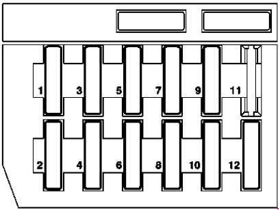
| No. | Fused function | A |
| 1 | Left fog lamp Right fog lamp |
15 |
| 2 | Rear fog lamp | 7.5 |
| 3 | Right front parking lamp Right taillamp |
7.5 |
| 4 | Left front parking lamp Left taillamp |
7.5 |
| 5 | Left high beam | 7.5 |
| 6 | License plate lamp Instrument illumination Symbol illumination Automatic headlamp range control |
7.5 |
| 7 | Right high beam High beam indicator lamp |
7.5 |
| 8 | Left low beam | 15 |
| 9 | Stop lamp Cruise control |
15 |
| 10 | Right low beam | 15 |
| 11 | Not used | – |
| 12 | Reverse lamp/turn signal lamp Rearview mirror dimming control Parking aid control |
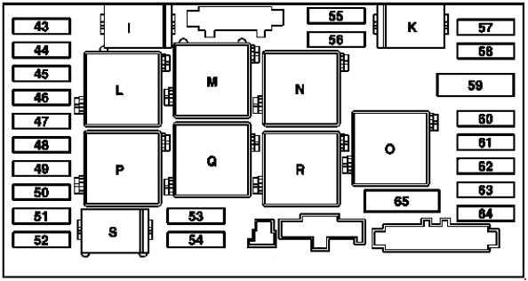
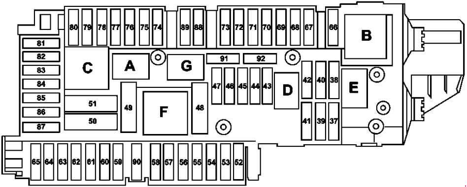
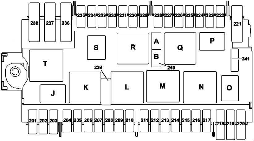
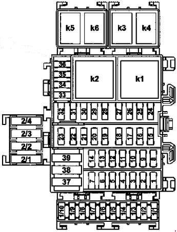
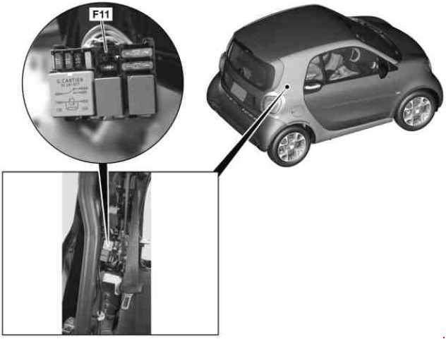
Fuse box in trunk
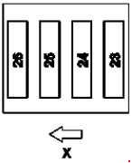
X – Front of vehicle
| No. | Fused function | A |
| 23 | Asra: Supply pump (CL) Horn (ATA) Trunk lamp |
20 |
| 24 | Asra: PSE control module | 40 |
| 25 | Asra: Soft top mechanism hydraulic unit | 30 |
| 26 | Asra: Not used | – |
Fusecard
170 545 01 00
170 545 10 00
170 545 20 00
170 545 22 00
170 545 28 00
WARNING: Terminal and harness assignments for individual connectors will vary depending on vehicle equipment level, model, and market.