Ford Freestar (2003 – 2007) – fuse box diagram
Year of production: 2003, 2004, 2005, 2006, 2007
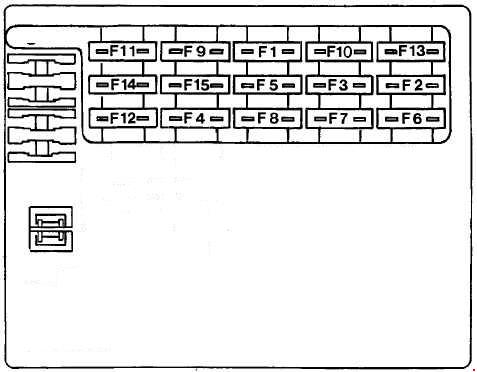
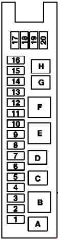
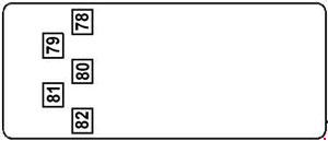
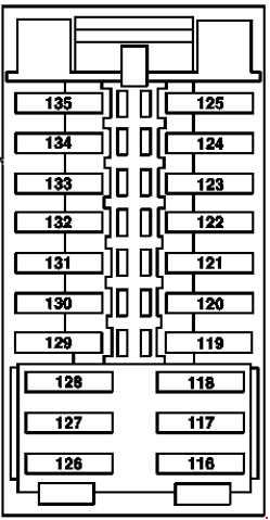
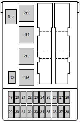
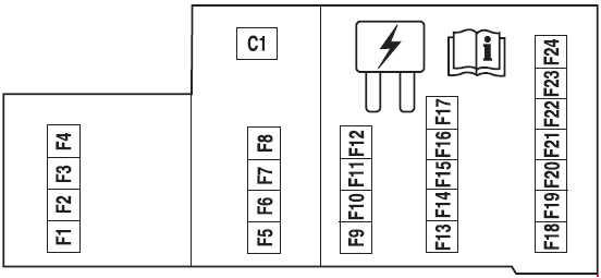
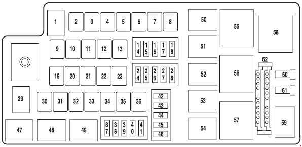
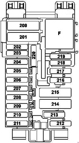
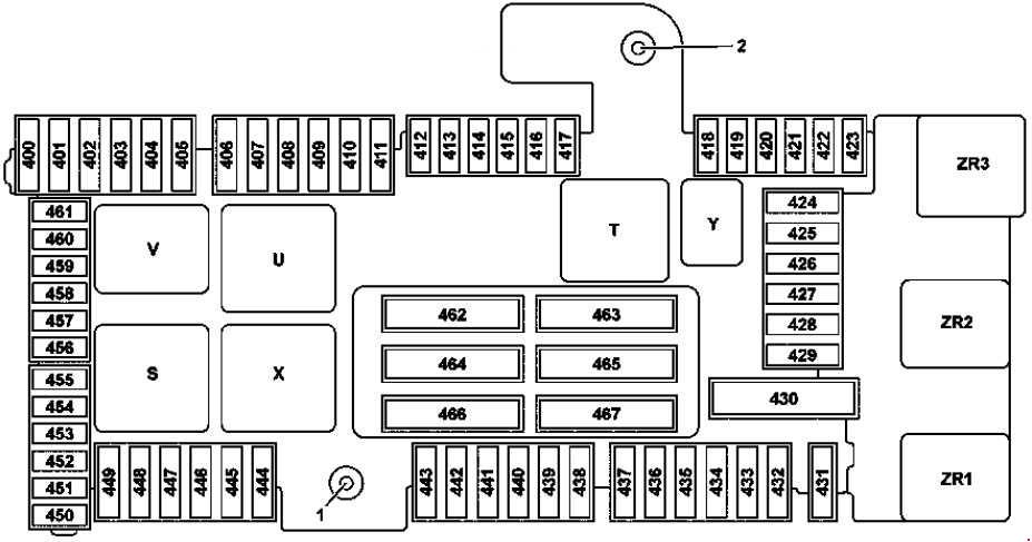
Passenger Compartment Fuse Panel
The fuse panel is located below and to the left of the steering wheel by the brake pedal.
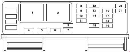
| Fuse | A | Circuit protected |
| 3 | 10 | Front wiper motor Run feed |
| 4 | 5 | B+ feed to outside mirrors |
| 5 | 20 | Vent window power feed/Radio feed |
| 6 | 5 | Driver door switch illumination/Passenger door switch illumination |
| 7 | 10 | Rear wiper Run feed |
| 8 | 10 | Cluster/Electronic Automatic Temperature Control (EATC) B+ feed, DVD |
| 9 | 10 | Passive Anti-theft System (PATS) LED feed |
| 10 | 5 | Auxiliary radio |
| 11 | 5 | Auxiliary climate control system/Power Liftgate Module/Left and right power sliding door module/Data Link Connector (DLC)/Clock B+ feeds |
| 12 | 5 | Brake-Shift Interlock (BSI) Run feed, Climate control system Run feed |
| 13 | 5 | Compass/Driver heated seat/Passenger heated seats/Reverse sensing system/Power Liftgate Module/Power sliding door Run feeds |
| 14 | 5 | Underhood fuse box Rim feed, Front blower Run feed |
| 15 | 10 | Brake On-Off (BOO) switch B+ |
| 16 | 5 | Steering angle/Cluster/Power sliding door and power liftgate inhibit LED/Electrochromatic mirror Run/Start/Tire Pressure Monitoring System (TPMS) |
| 17 | 10 | Restraint Control Module (RCM)/Passenger Air bag Disable Indicator (PADI)/Passenger Occupant Detection System (PODS) Run/Start |
| 18 | 10 | Anti-lock Brake System (ABS) module/Brake pressure switch/Speed control Run/Start |
| 19 | 5 | PATS/Cluster/Air bag LED/Powertrain Control Module (PCM) relay Run/Start |
| 20 | 10 | Liftgate Start feed, Radio Start feed |
| 21 | 10 | Starter relay power START |
| Relay | ||
| 1 | Accessory delay relay 1 | |
| 2 | Accessory delay relay 2 | |
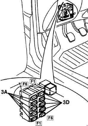
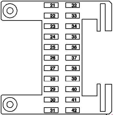
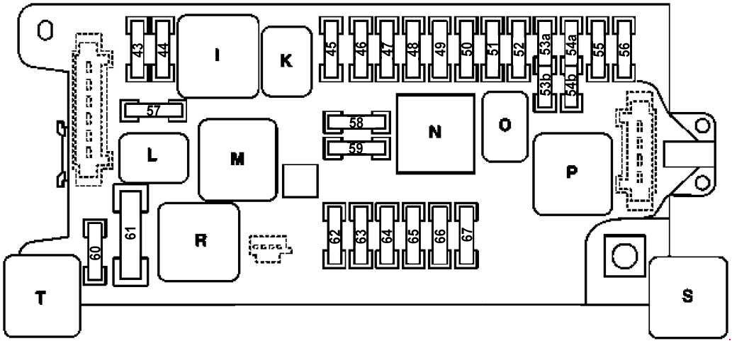
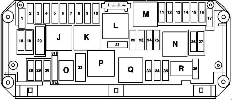
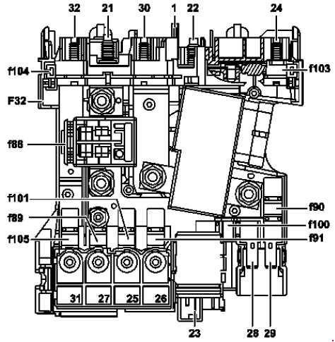
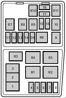
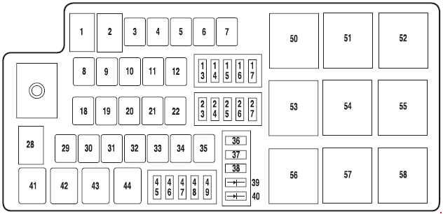
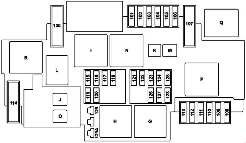
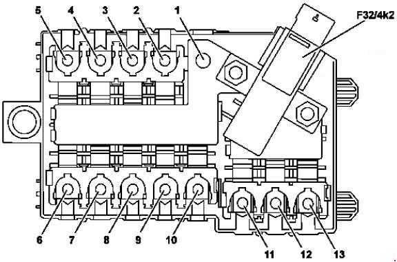
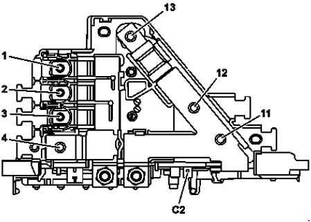
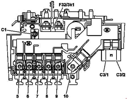
Fuse box in the engine compartment
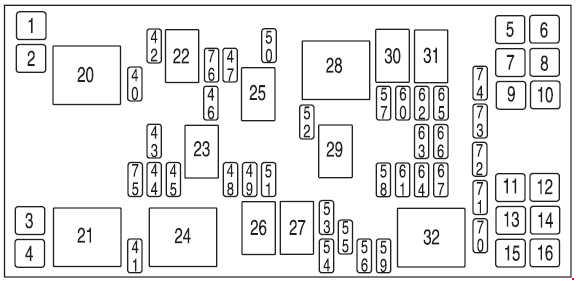
| Fuse | A | Circuit protected |
| 1 | — | — |
| 2 | 30 | Right cooling fan |
| 3 | 30 | Left cooling fan |
| 4 | 30 | Starter solenoid |
| 5 | 30 | Right-hand power sliding door |
| 6 | 30 | SJB accessory #2 (driver power window) |
| 7 | 30 | Auxiliary blower motor |
| 8 | 40 | Anti-lock Brake System (ABS) #2 (coil power) |
| 9 | 30 | Power liftgate |
| 10 | 30 | SJB accessory #1 (passenger window, radio, vent windows’) |
| 11 | 30 | Left, power seat/heated seat |
| 12 | 40 | ABS #1 (pump motor) |
| 13 | 40 | Rear defroster |
| 14 | 30 | Front climate control system blower motor |
| 15 | 30 | Right power seat/heated seat |
| 16 | 30 | Left-hand power sliding door |
| 40 | 15 | Engine #1 (A/C relay coil, IMRC, HEGO sensors, Canister purge, Transmission module, Canister vent) |
| 41 | 25 | Horn |
| 42 | 10 | A/C clutch |
| 43 | 15 | Engine #2 (Cooling fan relays, Injectors, PCM, MAF sensor, LAC, Ignition coil, ESM) |
| 44 | 10 | Heated PCV |
| 45 | 15 | High beams |
| 46 | 20 | Trailer stop/turn lamps |
| 47 | 15 | Fuel pump, Fuel pump shut-off switch |
| 48 | — | — |
| 49 | 10 | PCM KAP, Canister vent |
| 50 | 10 | Alternator |
| 51 | 10 | Adjustable pedals (non-memory) or memory module |
| 52 | 20 | Trailer tow park lamps |
| 53 | 10 | Heated mirrors |
| 54 | 30 | Front wiper motor |
| 55 | 25 | Rear wiper motor |
| 56 | 30 | Premium sound radio |
| 57 | 20 | Cigar lighter |
| 58 | 30 | SJB #1 – Center High-Mounted Stop Lamp (CHMSL), License plate lamps, OBD II, Dome lamp, Auxiliary blend doors, Switch illumination (feeds F-8, F-9, F-10 and F-ll) |
| 59 | 20 | Radio (non-premium) |
| 60 | 30 | SJB #4 – Back-up lamps, Door locks, Theft sounder |
| 61 | 20 | 3rd row power point |
| 62 | 30 | SJB #3 – Right cornering/auxiliary lamps, Right low beam, Left front park/turn lamps, Left rear park/stop/turn lamps, Instrument panel courtesy lamps, Step well lamps, Left signal mirror, Clock, Cluster, Message center (SJB F-15), Switch illumination for: overhead console, DVD/Rear climate control system, Headlamp switch illumination, Climate control illumination |
| 63 | 20 | Instrument panel power point, Cigar lighter |
| 64 | 20 | Ignition switch #1 feed |
| 65 | 30 | SJB #2 – Left cornering/auxiliary lamps, Left low beam, Right front park/turn lamps, Right rear park/stop/tum lamps, Puddle lamps, Mirror signals, Visors, 2nd and 3rd row lamps, Cargo lamp, Defroster indicator |
| 66 | 20 | 2nd and 3rd row seat power points |
| 67 | 20 | Ignition switch #2 feed |
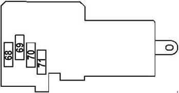
| 70 | — | — |
| 71 | — | — |
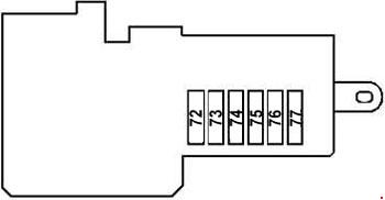
| 72 | — | — |
| 73 | — | — |
| 74 | — | — |
| Relay | ||
| 20 | Powertrain Control Module (PCM) power | |
| 21 | Horn | |
| 22 | A/C clutch | |
| 23 | High beams | |
| 24 | Starter | |
| 25 | Fuel pump | |
| 26 | — | |
| 27 | — | |
| 28 | Auxiliary blower | |
| 29 | Trailer park lamps | |
| 30 | Left trailer stop/turn lamps | |
| 31 | Right trailer stop/tum lamps | |
| 32 | Rear defroster | |
| Diode | ||
| 75 | PCM | |
| 76 | A/C clutch | |
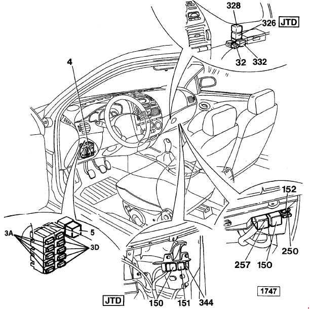
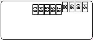
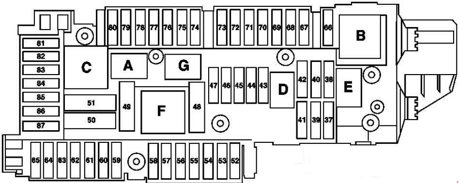
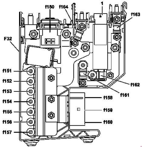
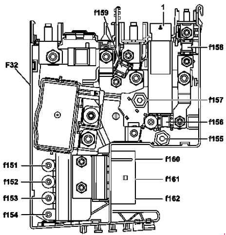
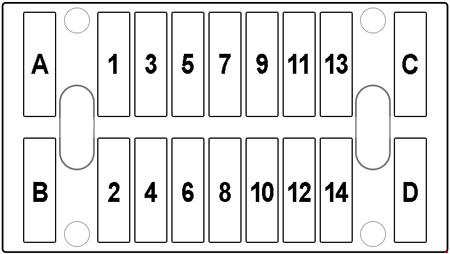
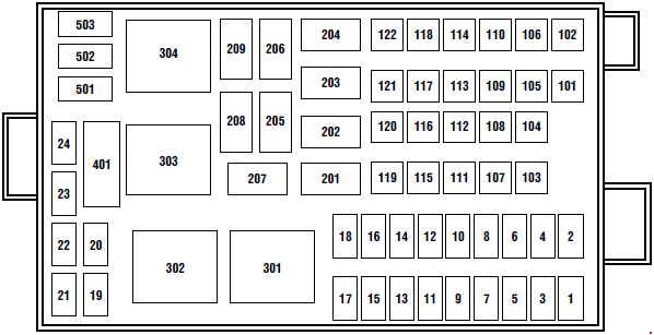
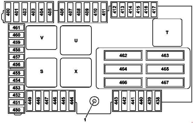
Auxiliary relay box (cooling fans)
The relay box is located in the engine compartment by the radiator.
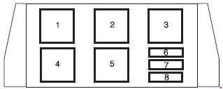
| Fuse | A | Circuit protected |
| 6 | 40 | Right-hand cooling fan motor (Vehicles with trailer tow package only) |
| 7 | 15 | Low-speed cooling fan circuit breaker (Vehicles with trailer tow package only) |
| 8 | 40 | Left-hand cooling fan motor (Vehicles with trailer tow package) |
| 10 | Low-speed cooling fan circuit breaker (Vehicles without trailer tow package) | |
| Relay | ||
| 1 | Cooling fan relay | |
| 2 | Cooling fan relay | |
| 3 | Cooling fan relay | |
| 4 | Cooling fan relay | |
| 5 | Cooling fan relay | |
WARNING: Terminal and harness assignments for individual connectors will vary depending on vehicle equipment level, model, and market.