Ford Taurus (2009 – 2017) – fuse box diagram
Year of production: 2009 ,2010, 2011, 2012, 2013, 2014, 2015, 2016, 2017
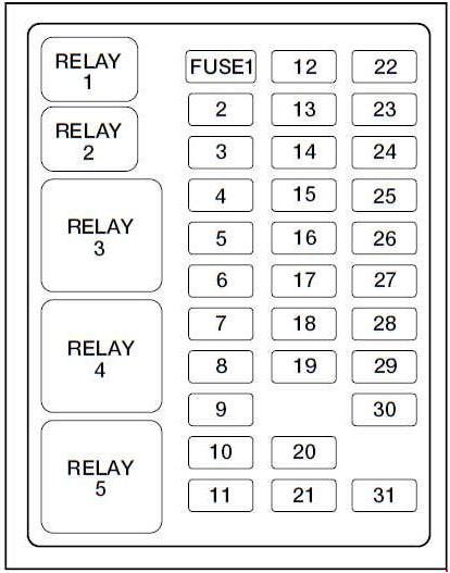
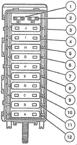
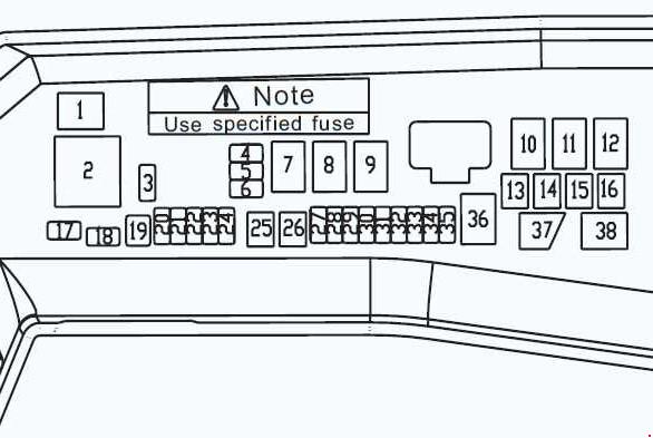
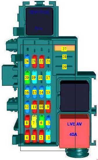
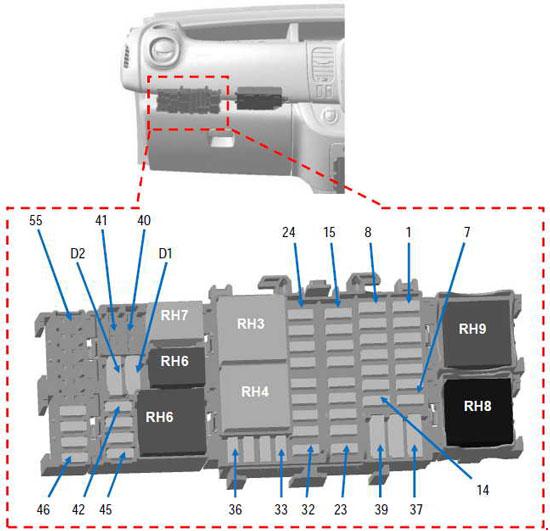
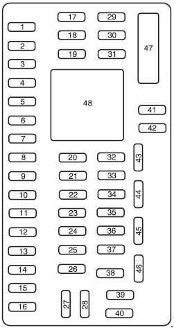
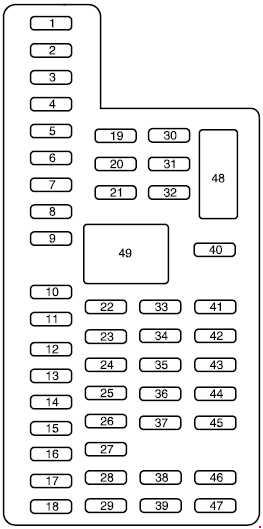
Passenger Compartment Fuse Panel (2009-2013)
| Number | A | Description |
| 1 | 30 | Left front power window, Smart window motor |
| 2 | 15 | Brake on/off switch |
| 3 | 15 | Driver power seat |
| 4 | 30 | Right front power window, Smart window motor |
| 5 | 10 | Transmission shifter solenoid, Keyless keypad |
| 6 | 20 | Turn signals, Hazard flashers |
| 7 | 10 | Low beam headlamps (left) |
| 8 | 10 | Low beam headlamps (right) |
| 9 | 15 | Interior lights, Cargo lamps |
| 10 | 15 | Switch illumination, Puddle lamps |
| 11 | 10 | All wheel drive (AWD) module |
| 12 | 7,5 | Passive entry/passive start (PEPS) module (2009-2010), Intelligent access (IA) module (2011-2012) |
| 13 | 5 | Memory seats, Mirrors, Keypad, PEPS receiver (2009-2010), Driver’s door module, IA receiver (2011-2012) |
| 14 | 10 | Navigation display, Memory seat, SYNC®, Center information display, GPS, Driver seat |
| 15 | 10 | Climate control |
| 16 | 15 | Electronic finish panel, Ambient lighting |
| 17 | 20 | Trunk release, Moon roof, Smart windows, Lock/unlock |
| 18 | 20 | Rear heated seats |
| 19 | 25 | Audio amplifier |
| 20 | 15 | Diagnostic connector (OBDII), Adjustable pedal motor |
| 21 | 15 | Daytime running lamps (DRL) control |
| 22 | 15 | Park lamps, License plate lamps, Auxiliary lamps |
| 23 | 15 | High beam headlamps |
| 24 | 20 | Horn |
| 25 | 10 | Demand lighting (battery saver) |
| 26 | 10 | Instrument panel cluster, Heads-up display |
| 27 | 20 | Ignition switch, PEPS (2009-2010), Front wipers, One-touch integrated start (OTIS), IA (2011-2012) |
| 28 | 5 | Start relay/Audio mute |
| 29 | 5 | Instrument panel cluster, Heads-up display |
| 30 | 5 | — |
| 31 | 10 | — |
| 32 | 10 | Airbag module |
| 33 | 10 | — |
| 34 | 5 | Anti-lock brake system (ABS), Electronic power steeling |
| 35 | 10 | Rear heated seats, AWD, Rear park assist, Steering angle sensor, Blind spot information system, Multi-contour seats |
| 36 | 5 | Passive anti-theft system (PATS) |
| 37 | 10 | — |
| 38 | 20 | Subwoofer, Speaker amplifier |
| 39 | 20 | Radio/navigation |
| 40 | 20 | — |
| 41 | 15 | Delayed accessory feeds |
| 42 | 10 | — |
| 43 | 10 | Rear window defroster, Front wipers, Automatic high beam controller, Rain sensor |
| 44 | 10 | — |
| 45 | 5 | Front wiper relay, Blower motor relay |
| 46 | 7,5 | Occupant classification sensor (OCS), Passenger airbag deactivation indicator (PADI) |
| 47 | 30 | Circuit Breaker: Front passenger power window, Rear power windows |
| Relay | ||
| 48 | Delayed accessory relay | |
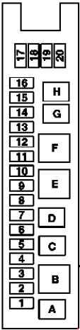
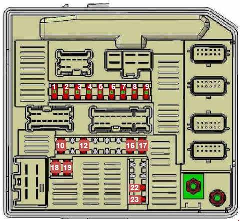
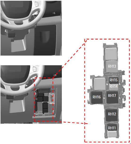
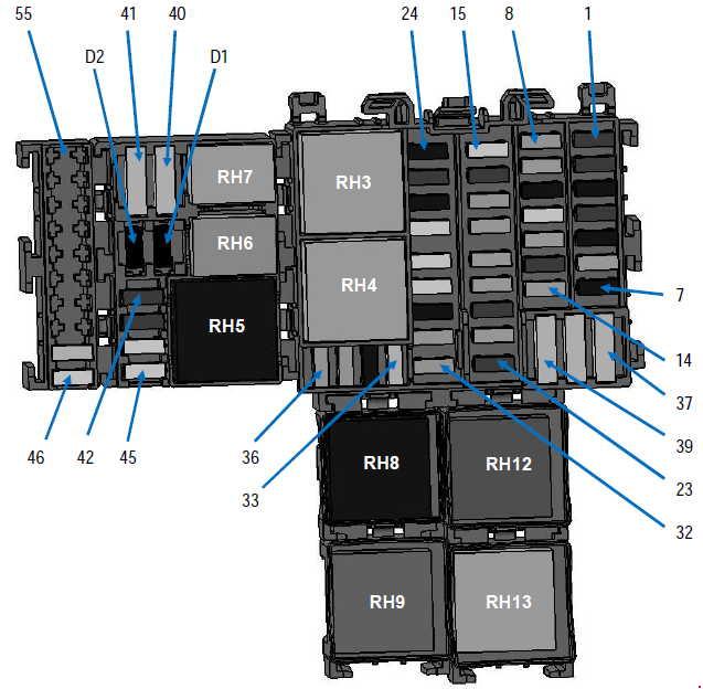
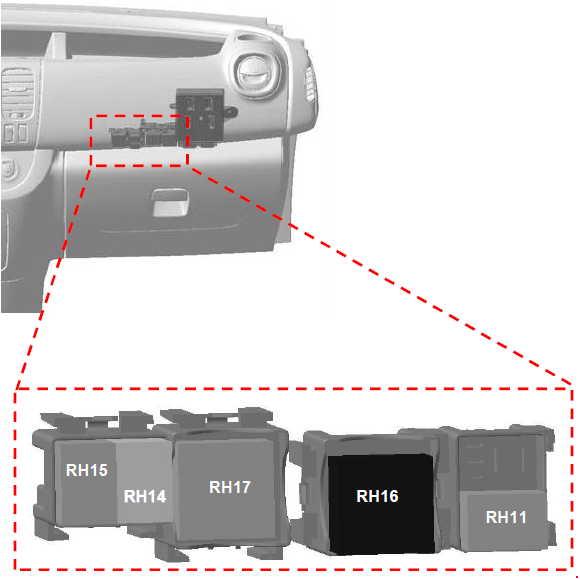
Passenger Compartment Fuse Panel (2013-present)
| Number | A | Description |
| 1 | 30 | Left front and right rear smart window motors |
| 2 | 15 | Driver seat switch |
| 3 | 30 | Right front smart window motor |
| 4 | 10 | Demand lamps battery saver relay and coil |
| 5 | 20 | Audio amplifier |
| 6 | 20 | — |
| 7 | 7,5 | Driver seat module logic, Left front door zone module, Keypad |
| 8 | 10 | — |
| 9 | 10 | SYNC module, Multi-function displays, Electronic finish panel, Radio frequency transceiver module |
| 10 | 10 | Run accessory relay |
| 11 | 10 | Intelligent access module logic, Heads-up display |
| 12 | 15 | Puddle lamp, Backlighting LED. Inter10r lighting |
| 13 | 15 | Right-hand direction Indicators |
| 14 | 15 | Left-hand direction Indicators |
| 15 | 15 | Stop lamp, Backup lamp |
| 16 | 10 | Right front low beam |
| 17 | 10 | Left front low beam |
| 18 | 10 | Start button, Keypad illumination, Brake shift interlock, Powertrain control module wakeup, Immobilizer transceiver module |
| 19 | 20 | Audio amplifiers |
| 20 | 20 | All lock motor relay and coil, Driver lock motor relay and coil |
| 21 | 10 | 2017: Extended power module |
| 22 | 20 | Horn relay |
| 23 | 15 | Steering wheel control module logic, Instrument cluster |
| 24 | 15 | Steering wheel control module, Datallnk |
| 25 | 15 | Decklld release |
| 26 | 5 | Ignition switch, Push button ignition switch |
| 27 | 20 | Intelligent access module power |
| 28 | 15 | — |
| 29 | 20 | Radio, Global positioning system module |
| 30 | 15 | Front park lamps |
| 31 | 5 | — |
| 32 | 15 | Smart window motors, Master window and mirror switch, Rear window power sunshade module, Lock switch illumination |
| 33 | 10 | — |
| 34 | 10 | Reverse park aid module, Automatic high beam and lane departure module, Rear heated seat module, Blind spot monitor module, Rear video camera |
| 35 | 5 | Motorized humidity sensor, Heads-up display, Traction control switch |
| 36 | 10 | Heated steering wheel |
| 37 | 10 | — |
| 38 | 10 | Auto–dimming mirror (without automatic high beam and lane departure module), Moonroof module and switch |
| 39 | 15 | High beams |
| 40 | 10 | Rear park lamps |
| 41 | 7,5 | Extended power module |
| 42 | 5 | — |
| 43 | 10 | — |
| 44 | 10 | — |
| 45 | 5 | — |
| 46 | 10 | Climate control module |
| 47 | 15 | — |
| 48 | 30 | Circuit breaker: Front passenger power window. Rear power windows |
| Relay | ||
| 49 | Delayed accessory | |
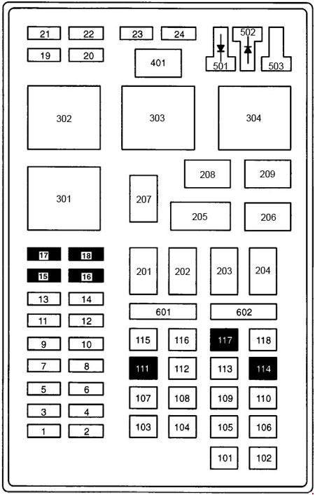
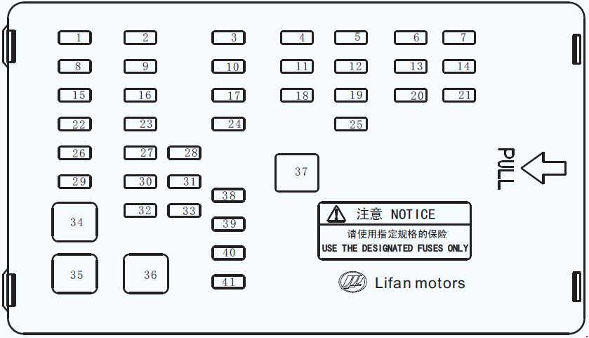
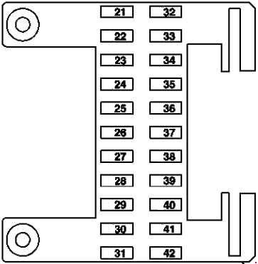
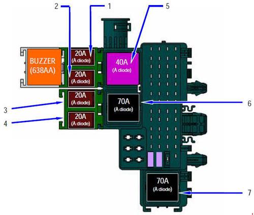
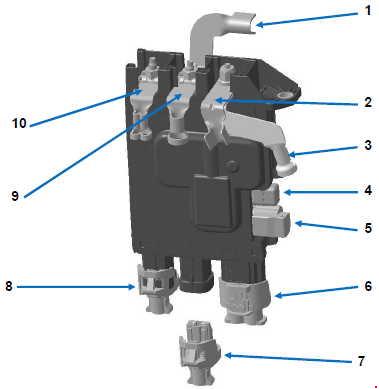
Fuse Box In The Engine Compartment (2009-2013)
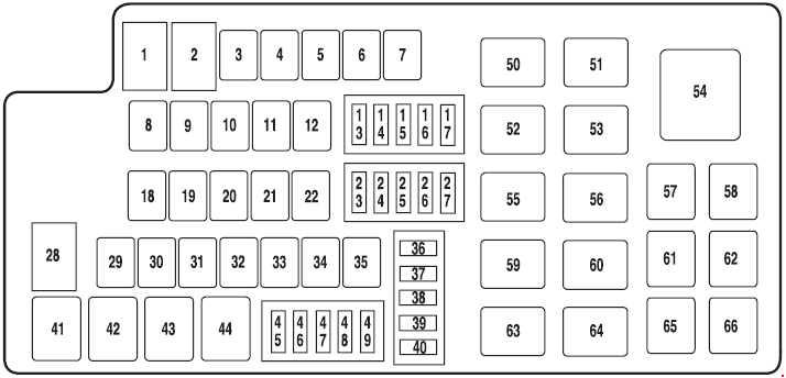
| Number | A | Description |
| 1 | 80 | Passenger compartment fuse panel power |
| 2 | 80 | Passenger compartment fuse panel power |
| 3 | — | — |
| 4 | 30 | Front wiper |
| 5 | 30 | Passenger seat |
| 6 | 20 | Cigar lighter |
| 7 | 60 | 2009-2010: Not used non-SHO engine (2011-2012): Engine cooling fan |
| 8 | 30 | Moon roof |
| 9 | 40 | Anti-lock brake system (ABS) pump |
| 10 | 30 | Starter relay |
| 11 | 30 | Powertrain Control Module (PCM) relay |
| 12 | 20 | ABS valve |
| 13 | 15 | Adaptive cruise control |
| 14 | — | — |
| 15 | — | — |
| 16 | 20 | Left headlamp |
| 17 | 10 | Alternator |
| 18 | — | — |
| 19 | 20 | Instrument panel power point |
| 20 | 40 | Rear window defroster |
| 21 | 20 | Console power point |
| 22 | 30 | Front heated or heated/cooled seats |
| 23 | 7,5 | Powertrain control module (PCM) (keep alive power), Canister vent |
| 24 | 10 | A/C clutch |
| 25 | 20 | Right headlamp |
| 26 | 10 | Backup relay |
| 27 | 25 | Fuel pump |
| 28 | 80 | 2009-2010: Engine cooling fan SHO engine (2011-2012): Engine cooling fan |
| 29 | — | — |
| 30 | — | — |
| 31 | — | — |
| 32 | 30 | Driver seat |
| 33 | 30 | Passive entry/passive start (PEPS) (2009-2010), Intelligent access (IA) (2011-2012) |
| 34 | — | — |
| 35 | 40 | Front heater blower |
| 36 | 20 | Passenger compartment fuse panel run/start |
| 37 | 10 | PCM relay |
| 38 | 5 | Delayed accessory |
| 45 | — | — |
| 46 | 15 | Vehicle power 2 (PCM), Vehicle power 3 (PCM) |
| 47 | 20 | Vehicle power 1 (PCM) |
| 48 | 20 | Vehicle power 4 (ignition coils) |
| 49 | 15 | Heated mirrors |
| Diode | ||
| 39 | Fuel diode (iVCT only) | |
| 40 | One-touch integrated start (OTIS) diode | |
| Relay | ||
| 41 | A/C clutch | |
| 42 | Fuel pump | |
| 43 | Backup lamps | |
| 44 | — | |
| 50 | Blower motor relay | |
| 51 | High-mount brake lamp w/ ACCM relay | |
| 52 | Starter relay | |
| 53 | PCM power relay | |
| 54 | — | |
| 55 | Front wiper relay | |
| 56 | Rear window defroster relay | |
| 57 | — | |
| 58 | — | |
| 59 | Left halogen headlamp relay | |
| 60 | Right halogen headlamp relay | |
| 61 | — | |
| 62 | — | |
| 63 | Daytime running lamps (DRL) 1 relay | |
| 64 | DRL 2 high beam control relay | |
| 65 | Run/start relay (PEPS) (2009-2010), Run/start relay (IA) (2011-2012) | |
| 66 | — | |
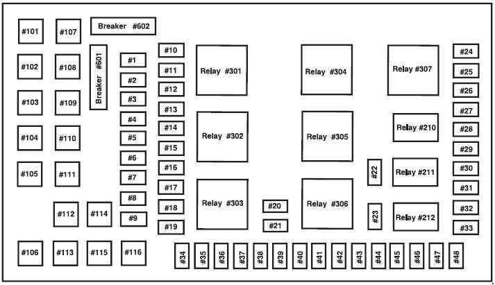
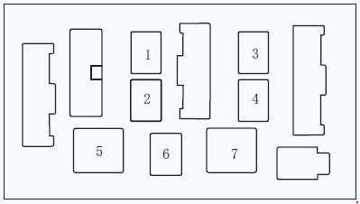
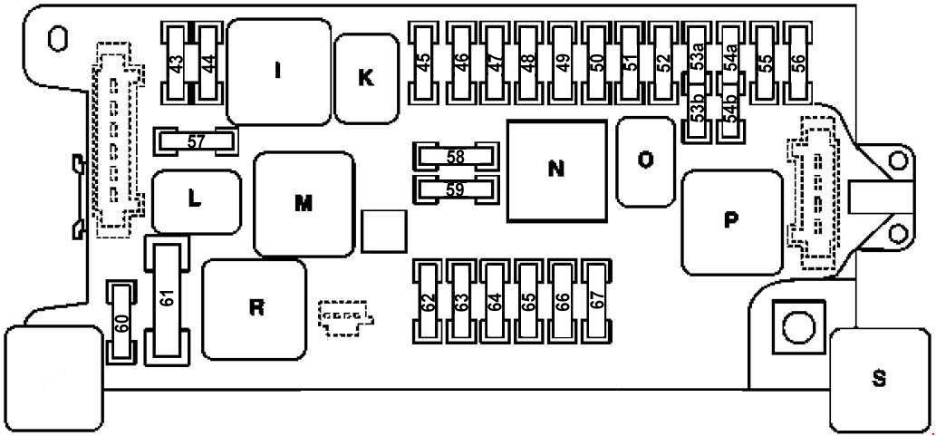
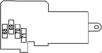
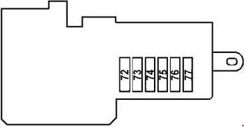
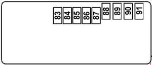
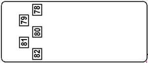
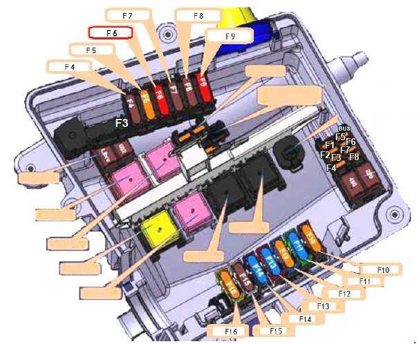
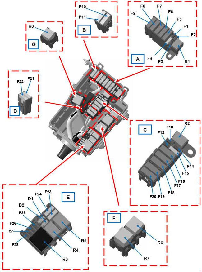
Fuse Box In The Engine Compartment (2013-present)
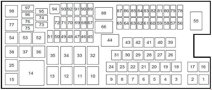
| Number | A | Description |
| 1 | — | — |
| 2 | — | — |
| 3 | — | — |
| 4 | 30 | Wiper motor relay |
| 5 | 50 | Anti-lock brake system pump |
| 6 | — | — |
| 7 | — | — |
| 8 | 20 | Moonroof, Power sunshade |
| 9 | 20 | Second row power point |
| 16 | — | — |
| 17 | — | — |
| 18 | 40 | Front blower motor relay |
| 19 | 30 | Starter relay |
| 20 | 20 | Storage bin power point |
| 21 | 20 | Rear heated seat module |
| 22 | — | — |
| 23 | 30 | Driver power seat, Memory module |
| 24 | — | — |
| 25 | — | — |
| 26 | 40 | Heated rear window relay |
| 27 | 20 | Cigar lighter |
| 28 | 30 | Climate controlled seats |
| 29 | 40 | Electric fan relay 1 |
| 30 | 40 | Electric fan relay 2 |
| 31 | 25 | Electric fan relay 3 |
| 39 | — | — |
| 40 | — | — |
| 41 | — | — |
| 42 | 30 | Passenger power seat |
| 43 | 20 | Anti-lock brake system valves |
| 45 | 5 | Rain sensor |
| 46 | — | — |
| 47 | — | — |
| 48 | — | — |
| 49 | — | — |
| 50 | 15 | Heated mirrors |
| 51 | — | — |
| 56 | — | — |
| 57 | 20 | Left high-intensity discharge headlamp |
| 58 | 10 | Alternator A-llne |
| 59 | 10 | Brake on/off switch |
| 60 | — | — |
| 61 | — | — |
| 62 | 10 | A/C clutch relay |
| 63 | — | — |
| 64 | 15 | Massage control seats |
| 65 | 30 | Fuel pump relay, Fuel Injectors |
| 67 | 20 | Oxygen sensor heater, Mass airflow sensor, Variable camshaft timing solenoid valve, Canister vent solenoid, Canister purge solenoid |
| 68 | 20 | Ignition coils |
| 69 | 20 | Vehicle power #1 (powertrain control module) |
| 70 | 15 | A/C clutch, Fan control relay coils (1-3), Variable air conditioning compressor, Auxiliary transmission warmup, Turbo charge waste-gate control, Electronic compressor bypass valve, All-wheel drive module, Positive crankcase ventilation heater |
| 71 | — | — |
| 72 | — | — |
| 73 | — | — |
| 74 | — | — |
| 75 | — | — |
| 76 | — | — |
| 78 | 20 | Right high-Intensity discharge headlamp |
| 79 | 5 | 2013: Adaptive cruise control module |
| 80 | — | — |
| 81 | — | — |
| 82 | — | — |
| 83 | — | — |
| 84 | — | — |
| 85 | — | — |
| 86 | 7,5 | Powertrain control module, Keep alive power and relay, Canister vent solenoid |
| 87 | 5 | Run/start relay |
| 89 | 5 | Front blower relay coil, Electrical power assist steering module |
| 90 | 10 | Powertrain control module run/start |
| 91 | 10 | Adaptive cruise control module |
| 92 | 10 | Anti-lock brake system module, Adaptive headlamp module (2013-2015) |
| 93 | 5 | Rear window defroster relay |
| 94 | 30 | Passenger compartment fuse panel run/start |
| 95 | — | — |
| 96 | — | — |
| 97 | — | — |
| Relay | ||
| 10 | — | |
| 11 | Heated rear window relay | |
| 12 | — | |
| 13 | Starter motor relay | |
| 14 | Left-hand cooling fan number 2 relay | |
| 15 | Fuel pump relay | |
| 32 | 2013: Not used 2014-2015: Power seat relay 2016-2017: Massage control seat relay |
|
| 33 | Right-hand cooling fan relay | |
| 34 | Blower motor relay | |
| 35 | Left-hand cooling fan number 1 relay | |
| 36 | — | |
| 37 | — | |
| 38 | — | |
| 44 | — | |
| 52 | — | |
| 53 | — | |
| 54 | — | |
| 55 | Wiper relay | |
| 66 | Powertrain control module relay | |
| 77 | — | |
| 88 | Run/start relay | |
| 98 | A/C clutch relay | |
WARNING: Terminal and harness assignments for individual connectors will vary depending on vehicle equipment level, model, and market.