Mercedes-Benz CL-Class c215 (1998 – 2005) – fuse box diagram
Year of production: 1998, 1999, 2000, 2001, 2002, 2003, 2004, 2005
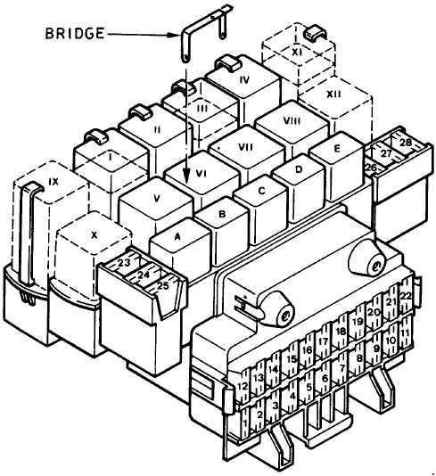
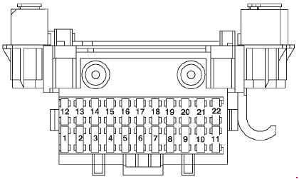
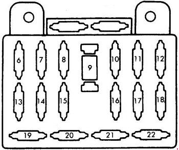
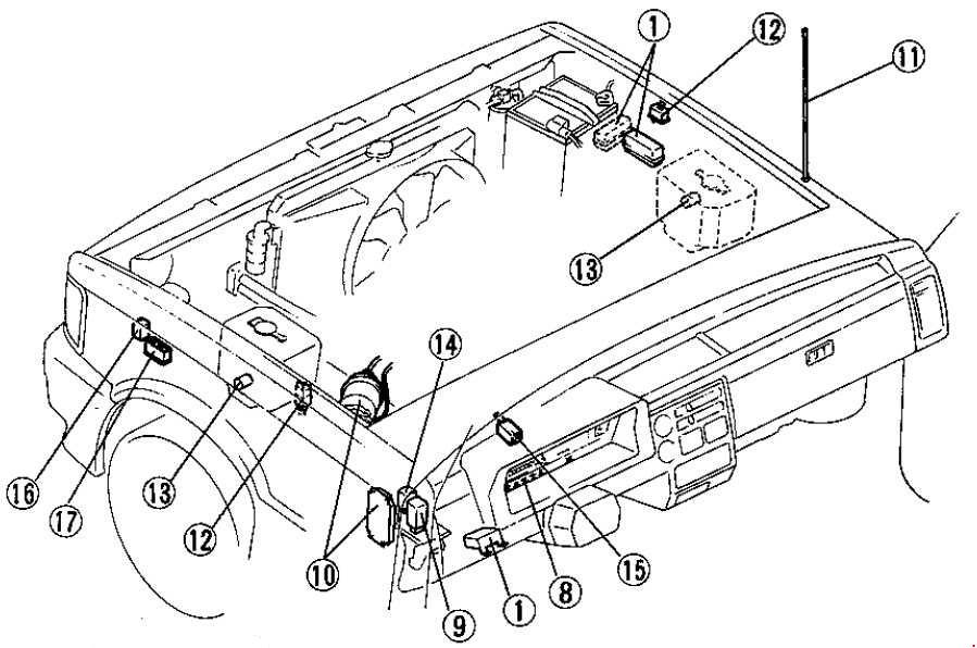
Fuse and relay box in engine compartment on left
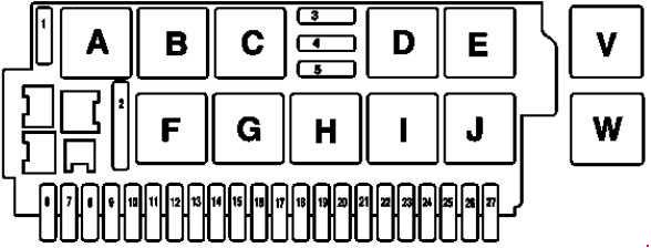
| Number | A | Description |
| 1 | 40 | Wiper park heater relay Special version: Not used |
| 2 | 50 | High pressure and return pump relay |
| 3 | 15 | Steering wheel adjustment, horizontal: S relay 1, jacket tube longitudinal adjustment S relay 2, jacket tube longitudinal adjustment |
| 4 | 15 | Steering wheel adjustment, vertical: S relay 1, jacket tube, height adjustment S relay 2, jacket tube height adjustment |
| 5 | 40 | Wiper On and Off relay |
| 6 | 7,5 | up to 31.8.02: Heater booster switch as of 1.9.02: Not used |
| 5 | Special version: Hydraulic brake | |
| 7 | 7,5 | Special version: 2nd three-phase alternator |
| 8 | 40 | Special version: Hydraulic brake |
| 9 | 30 | up to 31.8.03: Valid for air suspension: AIRmatic with ADS control module Valid for Active-Body-Control (ABC): ABC control module Special version: ADS, suspension contro |
| 20 | as of 1.9.03: Valid for air suspension: AIRmatic with ADS control module Valid for Active-Body-Control (ABC): ABC control module |
|
| 10 | 15 | Special version: Windshield wiper water pump Windshield washer water pump Circuit 15 connector sleeve Ignition coils |
| 11 | 15 | up to 31.8.02: Front cigar lighter with ashtray illumination |
| 5 | as of 1.9.02: VICS power supply separation point X137 | |
| 12 | 7,5 | up to 31.8.02: Sensor for vehicle-sensitive seat belt lock as of 1.9.02: Not used Special version: Sensor for left side airbag and window airbag Sensor for right side airbag and window airbag |
| 13 | 40 | Left front door control module |
| 14 | 5 | Special version: Hydraulic brake |
| 15 | 40 | Special version: Hydraulic brake |
| 16 | 7,5 | Stop light switch |
| 17 | 7,5 | C215: Vehicle-sensitive seat belt lock sensor |
| 18 | 5 | Valid for D-net portable CTEL (D2B) (preinstallation): Portable CTEL connector Valid for MB D-net telephone (D2B): D2B interface for permanently installed telephone Valid for MB D-net telephone (D2B) with Tele Aid emergency call system: TELE AID control module Valid for MB D-net telephone (D2B) with E-call emergency call system: D2B-Interface fixed installation Frequency selector control module Emergency call control module |
| 19 | 5 | up to 31.8.02: Not used as of 1.9.02: Left front reversible emergency tensioning retractor (W220) Right front reversible emergency tensioning retractor (W220) |
| 7,5 | Special version: Instrument cluster | |
| 20 | 5 | up to 31.8.02: Instrument cluster Datalink connector as of 1.9.02: Not used |
| 7,5 | Special version: Diagnostic cables connector sleeve: Instrument cluster Data link connector Separation point Compact wiring harness/diagnosis module II, cockpit Intermediate connector Diagnosis/taillamp wiring harness 16-pin Measuring connector Data link connector |
|
| 21 | 5 | up to 31.8.02: Instrument cluster as of 1.9.02: Not used |
| 7,5 | Special version:Instrument cluster | |
| 22 | 5 | up to 31.8.02: Instrument cluster |
| 15 | as of 1.9.02: COMAND operating, display and control unit | |
| 7,5 | as of 1.9.03; Japan version: COMAND operating, display and control unit Special version:Instrument cluster |
|
| 23 | 10 | up to 31.8.02: Climate control: AAC [KLA] control and operating module Circulation pump Left duovalve Right duovalve |
| 7,5 | as of 1.9.02 up to 31.8.03: TV tuner as of 1.9.02: Operating and display unit rear screen CD player with changer (in luggage compartment) |
|
| 24 | 10 | up to 31.8.02: Diagnostic connector |
| 20 | as of 1.9.02: Audio gateway control module | |
| 10 | Special version: Diagnostic cables connector sleeve: Instrument cluster Data link connector Separation point Compact wiring harness/diagnosis module II, cockpit Intermediate connector Diagnosis/taillamp wiring harness 16-pin Measuring connector Data link connector |
|
| 25 | 25 | up to 31.8.02: Not used as of 1.9.02: Sound amplifier` |
| 10 | Special version: Jacket tube module | |
| 26 | 10 | up to 31.8.02: Upper control panel control module as of 1.9.02: Not used |
| 27 | — | — |
| Relay |
||
| A | Wiper park heater relay |
|
| B | Relay for c.15 | |
| C | Relay for c.15R | |
| D | Steering column forward/back adjustment relay 1 | |
| E | Steering column forward/back adjustment relay 2 | |
| F | High pressure and return pump relay | |
| G | Wiper position 1 and 2 relay | |
| H | Wiper on and off relay | |
| I | Steering column height adjustment relay 1 | |
| J | Steering column height adjustment relay 2 | |
| V | Special version: Brake booster hydraulic unit relay | |
| W | Special version: Brake booster hydraulic unit safety relay | |
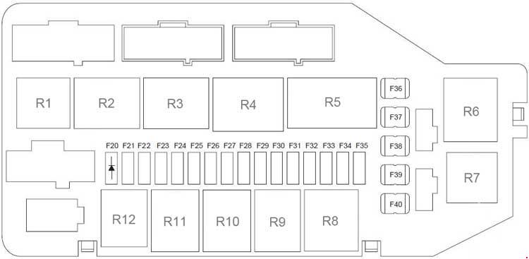
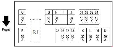
Fuse and relay box in engine compartment on right
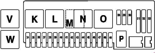
| Number | A | Description |
| 28 | 15 | Fanfare horns relay |
| 29 | 20 | Motor electronics/chassis relay |
| 10 | Special version: Motor electronics/chassis relay | |
| 30 | 20 | Motor electronics/chassis relay |
| 31 | 40 | Air pump relay |
| 32 | 40 | Air compressor relay |
| 33 | 40 | Heating systems recirculation unit |
| 60 | Special version: Electric suction-type fan | |
| 34 | 5 | up to 31.8.02: Traction system control module: Control module for ESP, SPS and BAS (electronic stability program (ESP), speed sensitive power steering (SPS), brake assist (BAS)) |
| 10 | as of 1.9.02: Traction system control module: Control module for ESP, SPS and BAS (electronic stability program (ESP), speed sensitive power steering (SPS), brake assist (BAS)) |
|
| 35 | — | up to 31.8.02: Not used |
| 15 | as of 1.9.02: Valid for steering wheel heater: DC/DC converter control unit | |
| 40 | Special version: Heating systems recirculation unit Blower regulator Blower motor |
|
| 36 | 7,5 | with Distronic: DTR control module |
| 37 | 15 | ETC [EGS] control unit Electronic selector lever module control unit VGS electric control unit |
| 38 | 5 | USA version:Luggage compartment interior button (KIT) |
| 39 | 40 | Right front door control module |
| 40 | 10 | With Xenon headlamps : Headlamp range adjustment control module |
| 41 | 20 | With stationary heater: STH radio remote control receiver STH heater unit (C215) STH heater unit or heater booster heater unit (W220) |
| 42 | 20 | Auxiliary air unit relay Special version: Transmission oil fan motor relay Engine oil fan unit: Temperature switch (100 °C) |
| 43 | 25 | Diesel engine only: CDI control module Starter relay, right front fuse and relay module Fuel pump relay (OM648 only) |
| 44 | 7,5 | OM613: CDI control module Intake manifold heating, right front fuse and relay module |
| 10 | OM628: CDI control module Starter relay, right front fuse and relay module Engine and AC electric suction fan with integrated control Charge fan circulation pump OM648: CDI control unit CDI relay AAC with integrated control additional fan motor |
|
| 45 | — | — |
| 46 | 5 | with Active-Body-Control (ABC): ABC control module with air suspension: AIRmatic with ADS control module |
| 47 | 10 | AAC multifunction sensor Control unit box blower motor Automatic air conditioning multifunction sensor (valid for right-hand drive) Coolant temperature switch (100 °C) |
| 7,5 | Special version: Multi-function sensor | |
| 48 | 7,5 | M112/113; up to 31.8.02: Suction-type fan control module M137; up to 31.8.02: Engine and AC electric suction fan with integrated control Special version: Suction fan control module |
| 49 | 15 | Ignition coil (T1/1) up to (T1/8) Radio interference suppression capacitor |
| 7,5 | Special version: Suction fan control module | |
| Relay |
||
| K | Engine electronics/chassis relay |
|
| L | Starter relay | |
| M | Only valid for diesel: CDI relay | |
| N | Secondary air pump relay | |
| O | Air compressor relay | |
| P | Fanfare horns relay | |
| V | Special version: Brake booster hydraulic unit relay | |
| W | Special version: Brake booster hydraulic unit safety relay | |
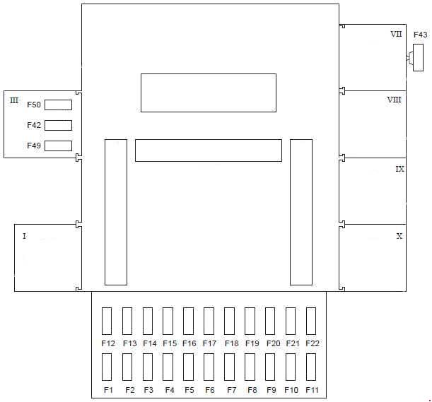
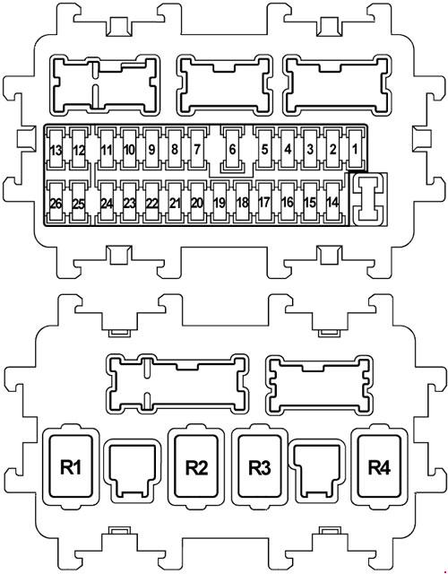
Fuse and relay box in rear
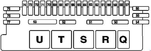
| Number | A | Description |
| 50 | 10 | Rear window roller blind relay |
| 51 | 5 | Towing sensor relay |
| 52 | 30 | Fuel pump relay |
| 53 | 50 | Rear window defroster relay |
| 54 | 10 | Trailer recognition control module Special version: Automatic fire warning and extinguishing system |
| 55 | 25 | Trailer hitch socket (13-pin) |
| 30 | Special version: PAS and special signal system | |
| 56 | 30 | Trailer recognition control module |
| 40 | Special version: Hydraulic window lift mechanism | |
| 57 | 25 | Valid for remote trunk locking (HDFS): Trunk lid open relay Trunk lid closed relay Remote trunk closing hydraulic pump Special version: Not used |
| 58 | 7,5 | Keyless Go: Keyless Go control module Keyless Go left front door antenna Keyless Go left rear door antenna (W220) Keyless Go left rear antenna (C215) Keyless Go right front door antenna Keyless Go right rear door antenna (W220) Keyless Go right rear antenna (C215) Keyless Go left front door lift solenoid Keyless Go left rear door lift solenoid (W220) Keyless Go right front door lift solenoid Keyless Go right rear door lift solenoid (W220) Special version: Automatic fire warning and extinguishing system |
| 59 | 30 | Taxi version:Special vehicle multifunction control module (SVMCM) Special version: PAS MCS |
| 60 | 7,5 | up to 31.8.02: Not used as of 1.9.02: Navigation processor VICS voltage supply separation point Rear window antenna amplifier module |
| 61 | 15 | up to 31.8.02: Radio Rear window antenna amplifier module CD player with changer (in luggage compartment) COMAND operating, display and control module Telephone circuit connector 15C TV tuner Video decoder Relief relay, circuit 15 Navigation processor Traffic data recorder |
| 7,5 | as of 1.9.02: Hands-free system control unit Voice control system control unit Portable CTEL connector E-Call control unit Telephone transmitter/receiver, D2B Selection switch for telephone handset, front and rear (W220) CTEL interface CTEL compensator Telephone interface Telephone transmitter/receiver and TELE AID, D2B Telecommunications control unit (as of 1.9.03) Bluetooth module (as of 1.9.03) Rear telephone handset (as of 1.9.03 W220) E-net compensator (as of 1.9.03) Operating and display unit display in rear (as of 1.9.03) GPS box control unit (as of 1.6.04) Universal Portable CTEL Interface (UPCI [UHI]) control unit (as of 1.6.04) Emergency call system control unit (as of 1.6.04) Special version: Not used |
|
| 62 | 20 | Pneumatic system equipment with combined functions ATA inclination sensor (Special version) |
| 63 | 7,5 | up to 31.8.02: D2B interface for permanently installed telephone CTEl transmitter / receiver if emergency call system (TELE AID) fitted, TELE AID control module Voice control system control module if emergency call system (TELE AID) fitted, Portable CTEL connector Traffic data recorder |
| 30 | as of 1.9.02: Pneumatic pump for dynamic seat control | |
| 64 | 7,5 | up to 31.8.02: COMAND operating, display and control module Rear window antenna amplifier module |
| 25 | as of 1.9.02: Left front seat adjustment control unit with memory | |
| 5 | Special version: D2B interface for permanently installed telephone D2B interface for portable cellular telephone |
|
| 65 | 5 | Special version: D2B interface for portable cellular telephone |
| 66 | 25 | up to 31.8.02:Sound amplifier as of 1.9.02: Right front seat adjustment control unit with memory |
| 7,5 | Special version: Interior lamp with universal joint | |
| 67 | 25 | Rear seats control module (not in the case of C215) |
| 68 | 15 | Rear air conditioning control module Rear AC refrigerant shutoff valve Delivery unit for rear heating system Circulation pump Left duovalve Right duovalve |
| 69 | 15 | Valid for rear air conditioning: Rear air conditioning control module |
| 70 | 10 | Tire pressure monitor control module |
| 71 | 25 | up to 31.8.02: Left front seat adjustment control module with memory |
| 40 | as of 1.9.02: Left front reversible emergency tensioning retractor | |
| 72 | 40 | Rear control unit (C215) Left rear door control module (W220) |
| 73 | 25 | up to 31.8.02: Right front seat adjustment control module with memory |
| 40 | as of 1.9.02: Right front reversible emergency tensioning retractor | |
| 74 | 40 | Rear control unit (C215) Right rear door control module (W220) |
| 75 | 10 | With Parktronic system: PTS control module |
| 76 | 15 | Rear backrest refrigerator box |
| 77 | 40 | Overhead control panel control unit |
| Relay | ||
| Q | Rear window roller blind relay | |
| R | Towing sensor relay | |
| S | Circuit 15 relay | |
| T | Fuel pump relay | |
| U | Rear window defroster relay | |
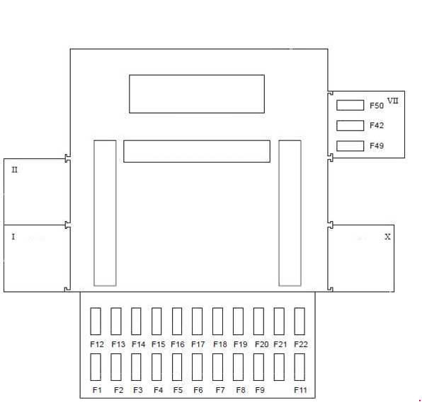
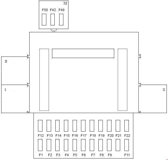
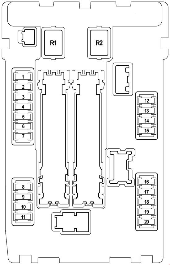
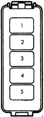
Fuse box in interior
Dashboard Fuse Box (LHD on R or passenger side and RHD on L or passenger side).
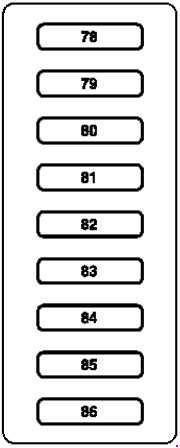
| Number | A | Description |
| 78 | 7,5 | Alarm signal horn with additional battery Steering column module EIS control unit ME-SFI control unit |
| 79 | 5 | Instrument cluster |
| 80 | 10 | Upper control panel control unit |
| 81 | 10 | Data link connector |
| 82 | 10 | AAC [KLA] control and operating unit Heating system delivery unit |
| 83 | 10 | Central gateway control unit |
| 84 | 5 | Instrument cluster Data link connector |
| 85 | 5 | Instrument cluster |
| 86 | 15 | Front cigar lighter with ashtray illumination |
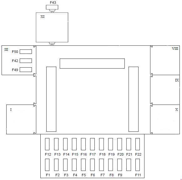
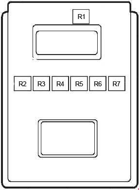
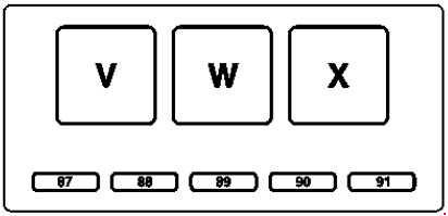
Fuse and relay box in right front of engine compartment
| Number | A | Description |
| 87 | 20 | Motronic relay |
| 88 | 20 | Motronic relay |
| 89 | — | — |
| 90 | 10 | Charge air cooler circulation pump |
| 91 | 10 | as of 1.9.03: Intank fuel pump |
| Relay | ||
| V | Motronic relay | |
| W | Charge air relay | |
| X | Intank fuel pump relay | |
WARNING: Terminal and harness assignments for individual connectors will vary depending on vehicle equipment level, model, and market.