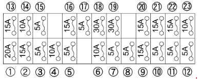
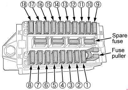
| Number |
Ampere rating [A] |
Description |
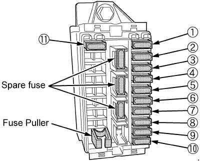
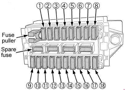
| 1 |
15 |
Audio |
| 2 |
5 |
Powertrain Control Module (PCM), Cluster |
| 3 |
20 |
Cigar lighter, Data link connector |
| 4 |
5 |
2000-2004: Power mirror switch, Mirror turn signal relays |
| 15 |
1997-1999: Autolamp Module, Remote Entry Module, Mirrors |
| 5 |
15 |
Speed control module, Reverse lamp, Climate mode switch, Daytime Running Lamps (DRL) relay, Digital Transmission Range (DTR) sensor (2001-2004), AC Clutch Relay (1997-1999) |
| 6 |
5 |
Cluster, Brake shift interlock solenoid, GEM, Rear Air Suspension Module (1997-1999) |
| 7 |
— |
— |
| 8 |
5 |
Radio, Remote entry module, GEM, In-vehicle entertainment system (SuperCrew only) |
| 9 |
— |
— |
| 10 |
— |
— |
| 11 |
30 |
Front washer pump relay, Wiper run/park relay, Wiper HI/LO relay, Windshield wiper motor |
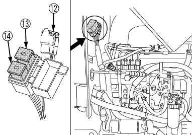
| 12 |
— |
— |
| 13 |
20 |
Stop lamp switch (Lamps), Turn/Hazard flasher, Speed Control Module (1997-2000) |
| 14 |
15 |
Battery saver relay, Interior lamp relay, Accessory Delay Relay (Power Windows) (1997-2000) |
| 15 |
5 |
Stop lamp switch (speed control, brake shift interlock, ABS (1997-2000), PCM Module Inputs (1997-2000)), GEM, Rear Anti-lock Brake System (RABS) module |
| 16 |
20 |
Headlamps (hi beams), Cluster (hi beam indicator) |
| 17 |
— |
— |
| 18 |
5 |
Instrument illumination (dimmer switch power) |
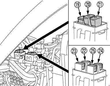
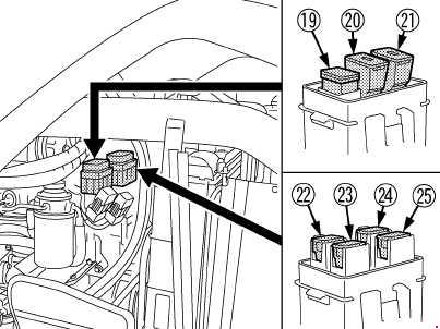
| 19 |
— |
— |
| 20 |
5 |
Audio, GEM, Powertrain Control Module (PCM), Transmission range sensor |
| 21 |
15 |
Clutch switch, Starter relay, I/P fuse 20, Digital Transmission Range (DTR) Sensor (2001-2004) |
| 22 |
10 |
Air bag module, Passenger air bag deactivation module |
| 23 |
10 |
Trailer tow battery Charge relay, Turn/Hazard flasher, 4×4 solenoids, 4×4 relays, Overhead console, 4-Wheel Anti-lock Brake System (4WABS) module, EC mirror, Heated seats |
| 24 |
10 |
2001-2004: Function selector switch assembly
1997-1999: Climate Mode Switch (Blower Relay) |
| 25 |
10 |
2003-2004: Heated mirrors |
| 5 |
1997-1999: 4 Wheel Anti-Lock Brake System (4WABS) Module |
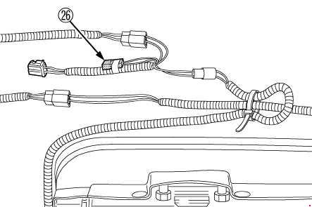
| 26 |
10 |
Right-hand low beam headlamp |
| 27 |
5 |
Foglamp relay and foglamp indicator, Main light switch (upstream) (2001-2004) |
| 28 |
10 |
Left-hand low beam headlamp |
| 29 |
5 |
Autolamp module, Transmission overdrive control switch, Central security module (2001-2004), Beltminder (2001-2004) |
| 30 |
30 |
Passive Anti-theft transceiver, Cluster, Ignition coils, PCM relay, Coil on plugs (2001-2004), Radio noise capacitor (2001-2004), ECC diode (2001-2004) |
| 31 |
— |
— |
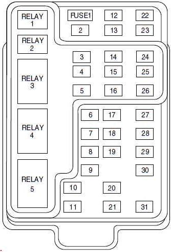
| Relay |
| R1 |
Interior lamp relay |
| R2 |
Battery saver relay |
| R3 |
— |
| R4 |
One-touch down window relay |
| R5 |
Accessory delay relay |