Vauxhall Monterey – fuse box diagram
Year of production:
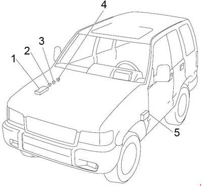
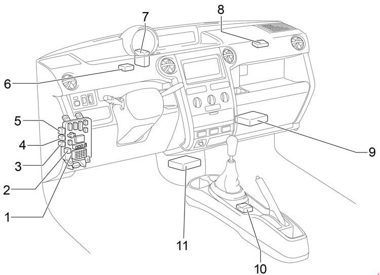
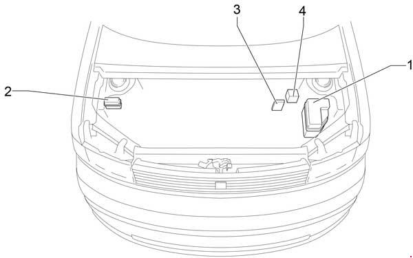
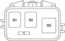
| Number | Description |
| 1 | Fuse Box |
| 2 | Glow Relay-1 |
| 3 | Glow Relay-2 |
| 4 | Starter Relay |
| 5 | Fuse Box |
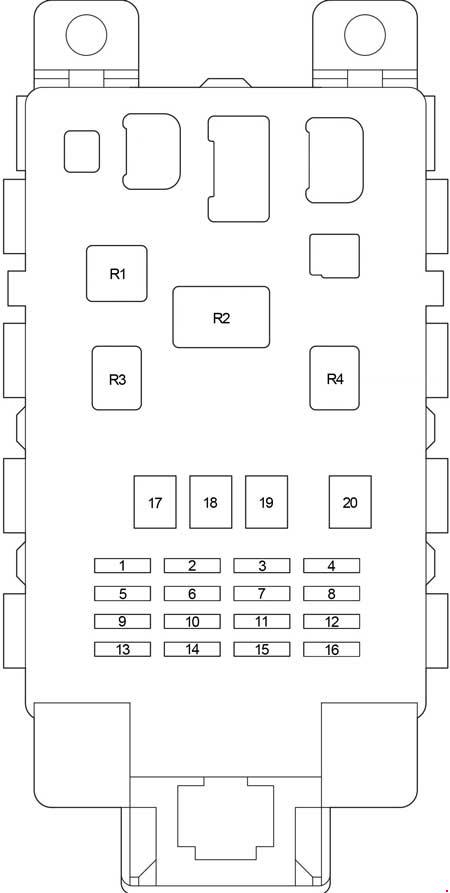
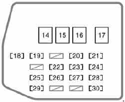
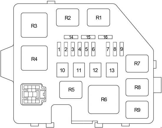
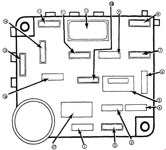
Engine Compartment Fuse Box
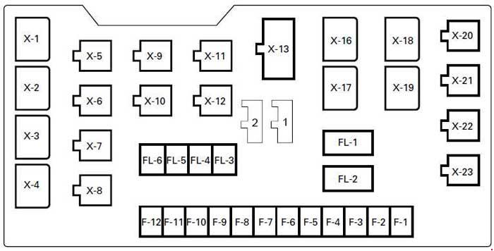
| Fuse | Ampere rating [A] | Circuit | |
| F1 | — | — | — |
| F2 | 10 | 02 SENSOR HEATER | Oxygen sensor |
| F3 | 15 | HORN HAZARD | Horn, Horn relay, Horn SW, Hazard warning SW, Flasher unit, Anti-theft horn, Anti-theft controller |
| F4 | 15 | H/LAMP-LH | Headlight (LH), High beam indicator light, Dimmer-passing SW, Cornering light SW, Fog light SW, Fog light relay, Cornering light, Cornering light relay |
| 10 | H/LAMP-LH (HI | Left−hand headlight (high beam) | |
| F5 | 15 | H/LAMP-RH | Headlight (RH), Dimmer-passing SW |
| 10 | H/LAMP-RH (HI) | Right−hand headlight (high beam) | |
| F6 | 10 | H/LAMP-LH (LOW) | Left−hand headlight (low beam) |
| F7 | 10 | H/LAMP-RH (LOW) | Right−hand headlight (low beam) |
| 15 | ANTI-THEFT | Anti-theft alarm system | |
| F8 | 15 | FRTFOG | Fog light, Fog light relay |
| 20 | FOG | Fog light, Fog light relay | |
| F9 | 20 | ABS | Hydraulic unit, Rear wheel anti-lock brake controller, Electronic brake control module |
| F10 | 15 | FUEL PUMP | Fuel pump |
| F11 | 10 | TAIL-LH | Tail light left-hand side |
| F12 | 15 | TAIL | Tail relay, Lighting SW, FRT side maker light, Parking light, Taillight, Trailer harness connector, Illumination controller, Illumination light, Glove box SW, License plate light, A/T shift indicator control unit |
| 10 | TAIL-RH | Tail light right-hand side | |
| Fusible Link | |||
| FL1 | 80 | MAIN | Battery |
| FL2 | 50 | KEY SW | Ignition switch, starter |
| FL3 | 50 | ECM | Engine Control Module Main Relay |
| FL4 | 30 | CONDENSER FAN | Condenser Fan |
| FL6 | 40 | (ABS 4-WHEEL ONLY) | ABS Hydraulic Unit, F9 Fuse (ABS) |
| Circuit Breaker | |||
| C/B-1 | — | — | — |
| C/B-2 | 30 | (P/W, P/S, S/R) | Power window relay, Power window SW, Power window motor, Sun roof motor, Sun roof control unit, Sun roof SW, Safety stop SW, Limit SW, Power seat switch, Front tilt motor & SW, Rear tilt motor & SW, Slide motor, Recliner motor & SW |
| Diode | |||
| 1 | Engine Control Module | ||
| 2 | Cornering light | ||
| Relay | |||
| X1 | Lighting | ||
| X2 | — | ||
| X3 | Dimmer | ||
| X4 | — | ||
| X5 | A/C Thermostat | ||
| X6 | — | ||
| X7 | A/C Compressor | ||
| X8 | Horn | ||
| X9 | Horn or Tail light |
||
| X10 | — | ||
| X11 | Fuel Pump | ||
| X12 | ECM Main | ||
| X13 | Windshield wiper int. | ||
| X14 | — | ||
| X15 | — | ||
| X16 | Upshift-1 (M/T) or Anti-theft Alarm System |
||
| X17 | Starter (Gasoline) Charge (Diesel) |
||
| X18 | Shift on the Fly | ||
| X19 | Condenser Fan | ||
| X20 | Cruise Control Main | ||
| X21 | Upshift-2 (M/T; with ABS) | ||
| X22 | Cornering Light or Rear Fog Light |
||
| X23 | Fog Light | ||
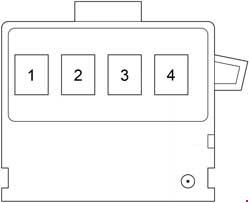
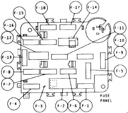
Passenger Compartment Fuse Box
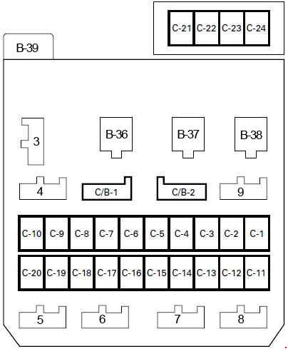
| Number | Fuse | Ampere ratting [A] | Description |
| C1 | 10 | STARTER RELAY | Starter relay, Clutch start SW (M/T), Mode SW (A/T), Anti-theft controller, DERM (SRS) |
| C2 | 15 | (SEAT HEATER) | Seat heater SW (LH & RH), Seat heater (LH & RH) |
| C3 | 15 | TURN BACK | Transmission control module, Turn signal SW, Front turn signal light, Rear turn signal light, Turn signal indicator light, Flasher unit, Cornering light relay, Backup light, Backup light SW (M/T), Mode SW (A/T), A/T shift indicator control unit, Lighting SW, A/T shift lock control unit, A/T shift indicator, Cruise control unit, Cancel SW |
| 10 | TURN BACK | Transmission control module, Turn signal SW, Front turn signal light, Rear turn signal light, Turn signal indicator light, Flasher unit, Cornering light relay, Backup light, Backup light SW (M/T), Mode SW (A/T), A/T shift indicator control unit, Lighting SW, A/T shift lock control unit, A/T shift indicator, Cruise control unit, Cancel SW | |
| C4 | 10 | ELEC. IGN. | Cruise control unit, Rear defogger SW, Rear defogger relay, Rear defogger SW indicator light, Clutch SW (M/T), Transmission SW-1, 2 (M/T), Transmission SW-3, 4 (M/T), Cancel SW (Combination SW), Cruise control main SW, Cruise control main relay, Cruise control indicator light, Cruise control SW, Door mirror, Door mirror defogger SW, A/T shift lock control unit, Power window relay, Electronic brake control module, Transmission control module, G sensor, Upshift-2 relay, Upshift indicator (Meter) |
| C5 | 15 | FRT WIPER & WASHER | Windshield wiper and washer SW, Windshield wiper motor, Windshield washer motor, Windshield wiper intermittent relay |
| C6 | 10 | RR WIPER & WASHER | Rear wiper & washer SW, Rear washer motor, Rear wiper motor, Rear wiper intermittent relay |
| C7 | 10 | (H/LAMP WIPER) | Headlight wiper SW, Headlight wiper motor, Headlight washer motor, Headlight wiper timer |
| C8 | 15 | ENGINE | Generator, ECM main relay, V.S.V; EGR, V.S.V: canister, V.S.V: intake air (DOHC) |
| C9 | 15 | IGN. COIL | Ignition control module, Engine control module |
| 15 | FUEL CUT | Fuel Cutout (4JG2) | |
| C10 | 10 | METER GAUGE | Vehicle speed sensor, Remind Buzzer, Meter and gauge (Voltmeter, Engine coolant temperature gauge, Tachometer, Speedometer, Oil pressure gauge, Fuel gauge), Indicator and warning light (Anti-lock brake system, Rear wheel anti-lock, Seat belt, check engine, Low fuel, 4WD, Oil pressure, Upshift, Brake system, Charge, A/T oil temp, Cruise control indicator light, Check trans indicator light, Power drive indicator light, Winter drive indicator light), 4WD SW, Parking brake SW, Seat belt SW, Brake differential SW Electronic brake control module, Engine control module, Rear wheel anti-lock brake controller |
| C11 | 10 | (AUDIO[ACC]) MIRROR | Audio, Door mirror, Door mirror control SW, Door mirror folding SW, Digital clock, Speaker |
| C12 | 20 | CIGARETTE | Cigarette lighter |
| C13 | 10 | ANTI THEFT | Anti-theft controller |
| C14 | 15 | STOP A/T CONT | Stoplight SW (w/o cruise control), Brake SW (w/cruise control), Rear wheel anti-lock brake controller, Stoplight, Transmission control module, Electronic brake control module, Trailer harness connector, Cruise control unit, A/T shift lock control unit, Lockup off relay |
| C15 | 20 | (AUDIO[BJ) | Horn, Horn relay, Horn SW, Hazard warning light SW, Flasher unit, Anti-theft horn, Hazard warning light, Audio |
| 20 | TELEPHONE | Telephone | |
| C16 | 10 | CLOCK[B] ROOM | Digital clock, Audio, Dome light, Map light, Luggage room light, Courtesy light, Door SW (Front, rear, tail gate), Antenna, Anti-theft controller, Key remind SW, Seat belt, Key & light remind buzzer |
| C17 | 25 | RR DEFOG | Rear defogger, Rear defogger relay |
| C18 | 20 | (DOOR LOCK) | Anti-theft indicator light, Front door lock & power window SW, Door lock key SW, Door lock actuator (Front & rear) |
| C19 | 25 | BLOWER | Blower motor, Blower resistor Fan SW |
| C20 | 10 | (AIR CON) | Pressure SW, A/C thermostat relay, A/C compressor relay, Magnetic clutch (A/C compressor), A/C SW, Electro thermostat, Fan SW |
| C21 | 10 | SRS-1 | SRS warning light (Meter) |
| C22 | 10 | SRS-2 | DERM |
| C23 | 10 | SRS-3 | Passenger inflator module, DERM |
| C24 | 10 | SRS-4 | Dual pole arming sensor, DERM, SRS coil assembly, Driver inflator module |
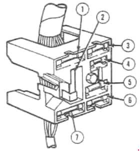
| Diode | |||
| 3 | Dome Light Anti-theft | ||
| 4 | Anti-theft (DOHC) | ||
| 5 | Anti-theft Light Remind | ||
| 6 | Mode Switch (DOHC) | ||
| 7 | Cruise Control RWAL (Rear Wheel Anti-Lock) | ||
| 8 | — | ||
| 9 | Electronic Brake Control Module (DOHC) | ||
| Relay | |||
| B36 | Heater and A/C | ||
| B37 | Power Window | ||
| B38 | Rear Defogger | ||
| B39 | Flasher Unit | ||
WARNING: Terminal and harness assignments for individual connectors will vary depending on vehicle equipment level, model, and market.