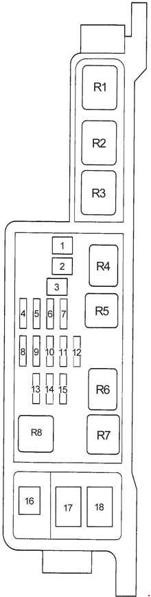
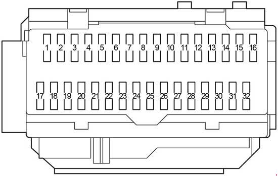
| Fuse/relay |
Ampere rating [A] |
Description |
| 1 |
15 |
2003-2004: Audio, CD changer
2005-2006: Taxi, Cluster, Lighting Control Module (Interior Lighting) |
| 10 |
2007-2012: Ignition (START) – Starter relay coil, DTRS |
| 2 |
5 |
2003-2004: Audio |
| 10 |
2005-2006: Ignition (ON) – Electronic Automatic Temperature Control (EATC) module, A/C mode switch (vehicles equipped with EATC only), A/C blower relay coil |
| 7,5 |
2007-2012: Power mirrors, Door lock switches, Mirror switch, Keypad switch, Decklid switch, DDM, Cluster |
| 3 |
7,5 |
2003-2004: Mirrors |
| 10 |
2005-2006:
EATC module (vehicles equipped with EATC only)
Audio (base audio system on vehicles not equipped with EATC) |
| 5 |
2007-2012: Ignition (START) – Audio mute, Police power distribution box (PDB) (Police vehicles only) |
| 4 |
10 |
2003-2004: Air bags
2005-2006: Ignition (ON) – Anti-lock Brake System (ABS) module, Rear Air Suspension Module (RASM), Variable Assist Power Steering (VAPS)
2007-2012: Lighting control module (LCM) (switch illumination), Autolamp sensor |
| 5 |
25 |
2003-2004: Package tray and rear flasher (Police vehicle options) |
| 10 |
2005-2006: Speed control deactivation switch, Stop signal, Brake-Transmission Shift Interlock (BTSI) (column-shift transmission) |
| 7,5 |
2007-2012: Ignition (ON/ACC) – LCM |
| 6 |
15 |
2003-2004: Instrument cluster warning lamps module, Overdrive control switch, Lighting Control Module (LCM), A/C clutch, Analog cluster |
| 10 |
2005-2006: Ignition (ON) – Cluster |
| 7,5 |
2007-2012: LCM |
| 7 |
10 |
2003-2004: Driver’s Door Module (DDM), Premium radio, Start input to police PDB (Police vehicle option)
2005-2006: LCM (Park lamps, Switch illumination)
2007-2012: Ignition (ON/ACC) – Wiper module |
| 8 |
25 |
2003-2004: Powertrain Control Module (PCM) power relay, Coil-on plugs, Radio noise capacitor, Passive Anti-Theft System (PATS) |
| 10 |
2005: Ignition (ON) – Rear Air Suspension Module (RASM), Variable Assist Power Steering (VAPS)
2006: LCM
2007-2012: Electronic automatic temperature control (EATC) module (vehicles equipped with EATC only) |
| 9 |
5 |
2003-2004: Transmission range sensor |
| 20 |
2005: LCM (Headlamps, Cornering lamps) |
| 10 |
2006: LCM (Switch illumination) |
| 7,5 |
2007-2012: Ignition (ON/ACC) – Door lock switch illumination, Heated seat switch illumination, Moon roof, Overhead console, Radio, Antenna, Electrochromatic mirror, Window relay coil (non-Police vehicles only), Window and decklid relay coil and Police ON/ACC relay coil (Police vehicles only) |
| 10 |
10 |
2003-2004: Rear window defrost, Heated mirrors |
| 5 |
2005-2006: Ignition (ON/START) – Driver’s Door Module (DDM), Police PDB (Police vehicles only) |
| 15 |
2007-2012: Hazards (non-Police vehicles only) |
| 20 |
2007-2012: Hazards (Police vehicles only) |
| 11 |
5 |
2003-2004: Traction control indicator relay (ABS w/traction control only) |
| 10 |
2005-2006:
Ignition (START) – ON/ACC (window) relay coil (non-Police vehicles only)
Ignition (START) – ON/ACC (window and decklid) relay coil and Police ON/ACC relay coil (Police vehicles only) |
| 15 |
2007-2012: Ignition (ON) – Turn signals |
| 12 |
15 |
2003-2004: Multi-function switch for turn/hazard lamps |
| 10 |
2005-2006: Ignition (ON/START) – Starter relay coil, DTRS |
| 15 |
2007-2012: Audio |
| 13 |
5 |
2003-2004: Radio |
| 10 |
2005-2006: Ignition (START) – Wiper module
2007-2012: Ignition (ON) – Anti-lock Brake System (ABS; 2007-2008) module, Rear Air Suspension Module (RASM), Variable Assist Power Steering (VAPS; 2007-2008), Cluster |
| 14 |
10 |
2003-2004: Anti-lock Brake System (ABS), Instrument Cluster
2005-2006: Ignition (ON) – BTSI (Floor-shift transmission) |
| 15 |
2007-2012: Taxi, Adjustable pedals |
| 15 |
15 |
2003-2004: Speed control module, Power relay coil (Police vehicle option), LCM, Clock, EATC blower motor relay, Door lock switch illumination, Heated seat switch, Moonroof |
| 7,5 |
2005-2006: Ignition (START) – LCM, Door lock switch illumination, Heated seat switch illumination, Moonroof, Overhead console, Electrochromatic mirror |
| 10 |
2007-2012: Ignition (ON) – EATC module, A/C mode switch (vehicles equipped with manual A/C only), A/C blower relay coil |
| 16 |
15 |
2003-2004: Reversing lamps, Shift lock, DRL module, VAP Steering, Electronic day/night mirror, Overhead console, Air suspension, 2005-2006: Climate control, Heated seat module, Speed chime module (GCC only), DDM, Back-up lamps
Ignition (ON) – Turn signals |
| 20 |
2007-2012: Cigar lighter (2007-2008), OBD II |
| 17 |
7,5 |
2003-2004: Wiper motor |
| 10 |
2005-2006: Ignition (START) – Audio
2007-2012: Ignition (ON) – A/C mode switch (vehicles equipped with manual A/C), Blend door, Heated seat modules, BTSI (Floor-shift transmission) |
| 18 |
10 |
2003-2004: Not used
2005-2006: Ignition (ON) – A/C mode switch (manual A/C only), Blend door, DDM, Heated seat modules, Daytime Running Lamps (DRL) module |
| 15 |
2007-2012: Lighting control module (interior lighting) |
| 19 |
15 |
2003-2004: Brake lamps, Brake signal for PCM, ABS and speed control module, DDM |
| 10 |
2005-2012: Left-hand low beam, DRL |
| 20 |
20 |
2003-2004: Spot lamp (Police vehicle option) |
| 10 |
2005-2012: Ignition (ON/ACC) – Back-up lamps, Anti-lock brake system (ABS; 2009-2012) |
| 21 |
15 |
2003-2004: LCM for park lamps and interior illumination, Autolamp/Sunload sensor |
| 10 |
2005-2012: Right-hand low beam, DRL |
| 22 |
20 |
2003-2004: Speed control servo, Multi-function switch for hazard lamps, Brake on/off switch, Feed for IP fuse 19 |
| 10 |
2005-2012: Ignition (ON/ACC) – Restraint Control Module (RCM), Occupant Classification Sensor (OCS), Passenger Air bag Deactivation Indicator (PADI) |
| 23 |
15 |
2003-2004: EATC module, Instrument cluster, Clock, LCM, Interior lamps, Door lock switches, Door ajar and roof lamps (Taxi vehicles)
2005-2012: Multi-function switch (Flash-to-pass), LCM (High beams; 2006-2012) |
| 24 |
10 |
2003-2004: Left-hand low beam
2005-2012: Ignition (ON/ACC) – Passive Anti-Theft System (PATS) module, Powertrain Control Module (PCM) relay coil, Fuel relay coil, Ignition coil relay coil |
| 25 |
15 |
2003-2004: Cigar lighter
2005-2006: Autolamp/Sunload sensor, Power mirrors, Door lock switches (DDM), Mirror switch, Keypad switch, Decklid switch, Adjustable pedal switch, DDM
2007-2012: LCM (Park lamps, corner lamps, license lamps) |
| 26 |
10 |
2003-2004: Right-hand low beam
2005-2006: Ignition (ON/ACC) – Analog cluster, Warning lamp module, LCM, Overdrive cancel switch, Rear defroster relay coil
2007-2012: Ignition (ON/START) – Cluster, LCM, Overdrive cancel switch, Traction control switch |
| 27 |
25 |
2003-2004: LCM for cornering lamps and high beam headlamps |
| 20 |
2005-2006: Cigar lighter, OBD II, Power point
2007-2012: Not used |
| 28 |
20 |
2003-2004: Power windows, DDM, Instrument panel/Door decklid release (police vehicles only) |
| 10 |
2005-2006: Center High-Mounted Stop Lamp (CHMSL) |
| 7,5 |
2007-2012: Brake signal, LCM (brake transmission shift interlock), ABS |
| 29 |
15 |
2003-2004: Not used
2005-2006: Audio |
| 2 |
2007-2012: Hazard in (Police vehicles only) |
| 30 |
15 |
2003-2004: Not used
2005-2006: Stop lamps, MFS |
| 2 |
2007-2012: Battery saver (Police vehicles only) |
| 31 |
15 |
2003-2004: Not used
2005-2006: Hazards (non-Police vehicles) |
| 20 |
2005-2006: Hazards (Police vehicles) |
| 5 |
2007-2012: Key in (LCM) |
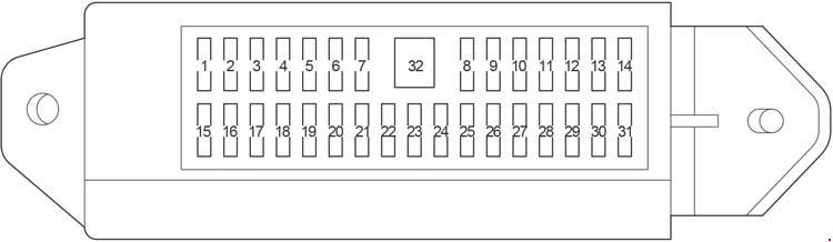
| 32 |
10 |
2003-2004: Not used
2005-2006: Mirror heaters, Rear defroster switch indicator |
| 2 |
2007-2012: Hazard out (Police vehicles only) |
| 33 |
10 |
Fire suppression module (if equipped) (Police vehicles only) |
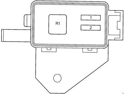
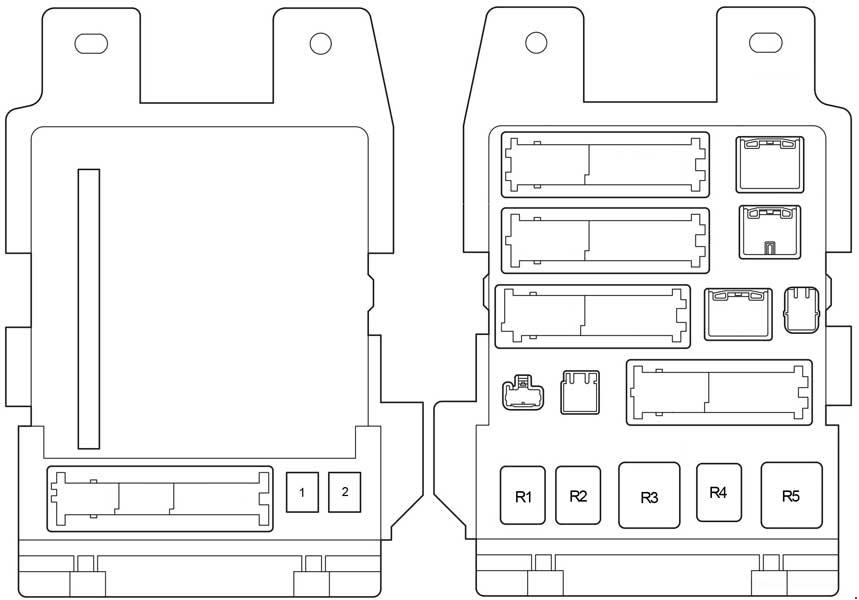
| Relay |
| K101 |
2005-2006: Rear defroster
2007-2012: Window relay, Decklid (Police vehicles only) |