Ford F-550 (2002 – 2007) – fuse box diagram
Year of production: 2002, 2003, 2004, 2005, 2006, 2007
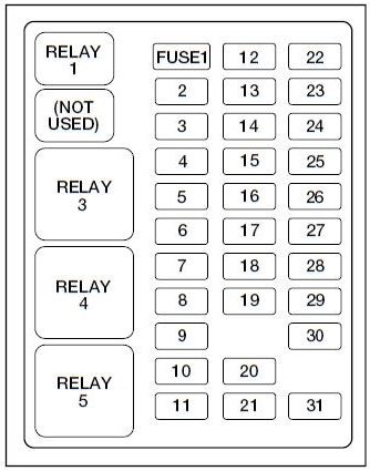
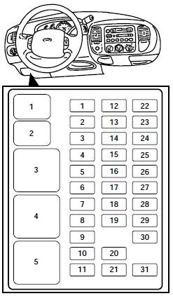
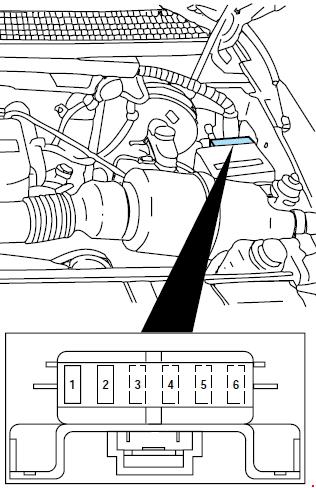
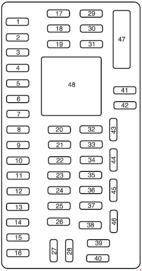
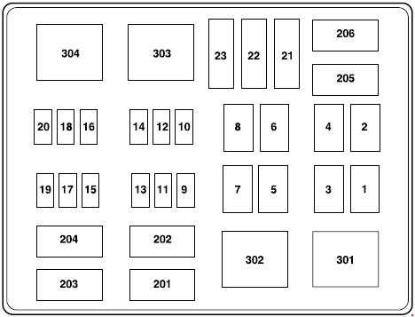
Passenger Compartment Fuse Box
The fuse panel is located below and to the left of the steering wheel by the brake pedal.
| Number | Ampere rating [A] | Description |
| 1 | 15 | Adjustable pedals |
| 2 | 10 | ’05-’07: Cluster |
| 3 | 10 | ’05-’07: Upfitter #3 |
| 4 | 20 | Power point – instrument panel |
| 5 | 10 | ’05-’07: Upfitter #4 |
| 6 | 20 | ’02-’04: Trailer tow turn/stop relay |
| 7 | 30 | High beam headlamps, Flash to pass |
| 8 | 15 | ’03-’04, Diesel: Back-up lamps |
| 20 | ’05-’07: Back-up lamps | |
| 9 | 20 | ’03-’04: Heated mirrors |
| 10 | 10 | ’02-’04: A/C clutch |
| 11 | 20 | Radio (main) |
| 12 | 20 | Cigar lighter, OBD II |
| 13 | 5 | Power mirrors/switches |
| 14 | 15 | ’02-’04: Daytime running lamps (DRL) |
| 15 | — | — |
| 16 | — | — |
| 17 | 15 | Exterior lamps |
| 18 | 20 | Turn lamps (flasher), Brake On-Off (BOO) lamps |
| 19 | 10 | Body security module, 4×4 module |
| 20 | 10 | ’03-’04, Diesel: Fuel Injection Control Module (FICM) relay |
| 15 | ’05-’07: Trailer tow Electric Brake Controller (EBC) | |
| 21 | 20 | ’05-’07: Heated seats |
| 22 | 20 | Engine control |
| 23 | 20 | Gasoline: Engine control Diesel: Climate control |
| 24 | 2 | ’03-’04: Brake pressure switch, Speed control |
| 15 | ’05-’07: Tow haul, Blower relay, Electronic Automatic Temperature Control | |
| 25 | 10 | ’02-’04: 4-Wheel Anti-lock Brake System (4WABS) module, Variable Fan Control (VFC) (’03-’04, Diesel) |
| 26 | 10 | Air bags |
| 27 | 15 | Ignition switch Run feed |
| 28 | 10 | ’02-’04: EATC module, Front blower relay coil ’05-’07: Trailer tow EBC logic |
| 29 | 10 | Customer access |
| 30 | 15 | Highbeam headlamps |
| 31 | 15 | ’02-’04: Clutch interlock switch (manual transmissions only), Transmission range sensor (automatic transmissions only) then to starter relay coil (all transmissions), 4×4 ’05: 4×4 ’06-’07: Starter relay |
| 32 | 5 | Radio (start) |
| 33 | 15 | ’02-’04: Front wiper ’05-’07: Cluster, 4×4, Wipers |
| 34 | 10 | Brake on-off switch (Low current) |
| 35 | 10 | Instrument cluster |
| 36 | 10 | ’02-’04: PCM Memory |
| 37 | 15 | Horn |
| 38 | 20 | Trailer tow park lamps, backup lamps (’02) |
| 39 | 15 | ’03-’04: Trailer tow back-up lamps ’05-’07: Heated mirrors |
| 40 | 20 | Fuel pump |
| 41 | 10 | Instrument cluster |
| 42 | 15 | Delayed accessory |
| 43 | 10 | Fog lamps |
| 44 | — | — |
| 45 | 10 | Ignition switch Run/Start feed |
| 46 | 10 | Left-hand low beam |
| 47 | 10 | Right-hand low beam |
| 48 | — | — |
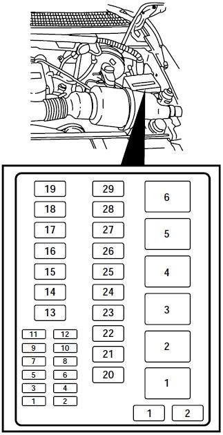
| 101 | 30 | Trailer tow electric brake |
| 102 | 30 | Door locks/Body security module |
| 103 | 50 | ’02-’04: Ignition switch |
| 30 | ’05-’07: Ignition switch | |
| 104 | 40 | ’03-’04: Heated backlight |
| 105 | 30 | ’02, Diesel: Injector driver module ’03-’04, Diesel: Fuel heater |
| 106 | 30 | Front wiper main |
| 107 | 40 | ’02-’04: Front blower motor |
| 20 | ’05-’07: Trailer tow battery charge | |
| 108 | 30 | ’05-’07: Upfitter #1 |
| 109 | 30 | ’02-’04: Heated seats ’05-’07: Upfitter #2 |
| 110 | 50 | ’02-’04: Ignition switch |
| 30 | ’05-’07: Ignition switch | |
| 111 | 30 | ’02-’04: 4WD/Shift on the fly |
| 112 | 30 | Left-hand power seats |
| 113 | 30 | Starter motor |
| 114 | 30 | Right-hand power seats |
| 115 | 20 | ’02-’04: Trailer tow battery charge ’05-’07: Upfitter control |
| 116 | 30 | Ignition switch |
| 601 | 30 | Circuit Breaker: Delayed accessory, Power windows, Moonroof |
| 602 | 60 | ’02-’04: 4WABS module |
| Relay | ||
| 210 | — | |
| 211 | ’03-’04, Diesel: Back-up lamps ’05-’07: Back-up lamps |
|
| 212 | — | |
| 301 | ’02-’04: Front blower motor ’05-’07: Trailer tow battery charge |
|
| 302 | Powertrain Control Module (PCM) | |
| 303 | ’02, Diesel: Injector driver module ’03-’04, Diesel: Fuel heater |
|
| 304 | ’03-’04: Heated backlight | |
| 305 | ’02-’04: Trailer tow battery charge ’05-’07: Upfitter control |
|
| 306 | Delayed accessory | |
| 307 | Starter | |
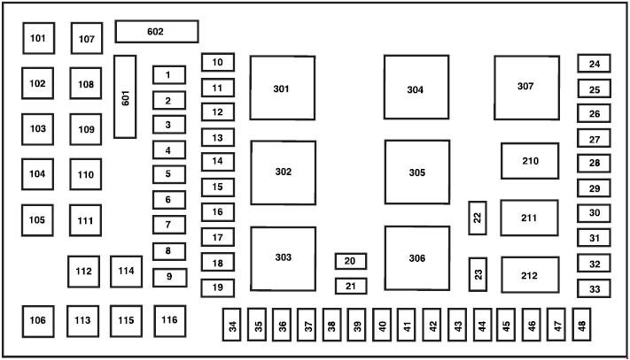
Engine Compartment Fuse Box (’05-’07)
| Number | Ampere rating [A] | Description |
| 1 | 30 | Wipers |
| 2 | 40 | Blower |
| 3 | 30 | Electronic Shift on the Fly (ESOF) |
| 4 | — | — |
| 5 | 50 | Diesel: Injector Driver Module (IDM) |
| 6 | — | — |
| 7 | 30 | ”05, Diesel: Horizontal Fuel Conditioner Module (HFCM) |
| 8 | — | Shunt |
| 9 | 20 | Trailer tow turn signals |
| 10 | 10 | Powertrain Control Module (PCM) keep alive power, Canister vent solenoid (gasoline) |
| 11 | 10 | Anti-lock Brake System (ABS) |
| 12 | 2 | Brake pressure switch |
| 13 | 15 | Daytime Running Lamps (DRL) |
| 14 | — | — |
| 15 | 15 | Diesel: Injector Driver Module logic |
| 16 | — | — |
| 17 | 10 | A/C clutch |
| 18 | 10 | Diesel: Injector Driver Module relay |
| 19 | — | — |
| 20 | 10 | Trailer tow back-up lamps |
| 21 | — | — |
| 22 | 60 | ABS (Coils) |
| 23 | 60 | ABS (Pump) |
| Relay | ||
| 201 | Trailer tow right turn signal/stop lamp | |
| 202 | Trailer tow left turn signal/stop lamp | |
| 203 | A/C clutch | |
| 204 | — | |
| 205 | Daytime Running Lamps #1 | |
| 206 | Daytime Running Lamps #2 | |
| 301 | Daytime Running Lamps #3 | |
| 302 | — | |
| 303 | Blower | |
| 304 | Diesel: Injector Driver Module | |
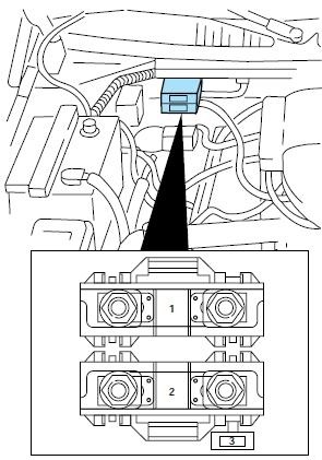
Auxiliary Relay Box (’06-’07)
An auxiliary relay box is located in the left-hand front side of the engine compartment. This box contains relays for the Electronic Shift On the Fly (ESOF) system.
WARNING: Terminal and harness assignments for individual connectors will vary depending on vehicle equipment level, model, and market.