Ford F-450 (2008 – 2010) – fuse box diagram
Year of production: 2008, 2009, 2010
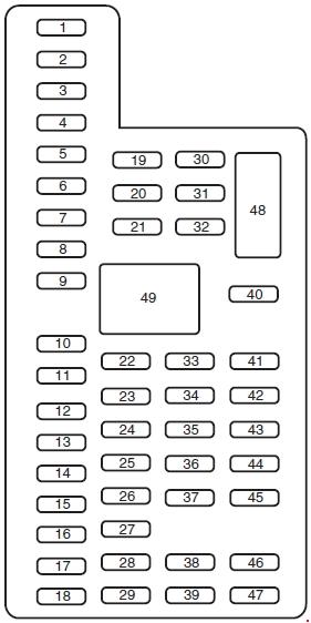
Passenger Compartment Fuse Box
The fuse panel is located in the passenger’s footwell.
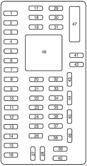
| Number | Ampere rating [A] | Description |
| 1 | 30 | — |
| 2 | 15 | — |
| 3 | 15 | Family Entertainment System (FES) |
| 4 | 30 | — |
| 5 | 10 | Keypad illumination, Brake-Shift Interlock (BSI), SPBJB |
| 6 | 20 | Turn signals |
| 7 | 10 | Left headlamp (Low beam) |
| 8 | 10 | Right headlamp (Low beam) |
| 9 | 15 | Interior lighting, Lighted running boards |
| 10 | 15 | Cargo lamp, Puddle lamp, Switch backlight |
| 11 | 10 | — |
| 12 | 7,5 | Power mirror switch, Driver power seat (Memory) |
| 13 | 5 | — |
| 14 | 10 | Upfitter relay #3 feed |
| 15 | 10 | Climate control head |
| 16 | 15 | Upfitter Relay #4 Feed |
| 17 | 20 | All lock motor feeds |
| 18 | 20 | Heated seat relay feed |
| 19 | 25 | — |
| 20 | 15 | Adjustable pedals, Datalink |
| 21 | 15 | Fog lamp relay feed, Cornering lamps |
| 22 | 15 | Park lamp relay feed |
| 23 | 15 | High beam headlight relay feed |
| 24 | 20 | Horn relay feed |
| 25 | 10 | Power telescoping mirror switch Demand lamps – underhood and illuminated visor (battery saver) |
| 26 | 10 | Cluster |
| 27 | 20 | Ignition switch feed, Passenger compartment fuses 28, 42, 43, 44, and 45, Engine compartment starter relay coil #57 (Diesel engine), Accessory shutoff control module (if equipped) (Diesel engine), Engine compartment starter relay diode (gasoline engines) |
| 28 | 5 | Radio |
| 29 | 5 | — |
| 30 | 5 | — |
| 31 | 10 | Compass |
| 32 | 10 | Restraints Control Module (RCM), Passenger Airbag Deactivation Indicator |
| 33 | 10 | Trailer tow brake controller, Trailer tow battery charge relay coil |
| 34 | 5 | — |
| 35 | 10 | Reverse Sensing System (RSS), 4×4 module, 4×4 solenoid, Traction control switch, Tow/Haul switch (Diesel engine) |
| 36 | 5 | Passive Anti-Theft System (PATS) transceiver, Cluster control |
| 37 | 10 | Dual automatic or Manual climate control, PTC control |
| 38 | 20 | Subwoofer |
| 39 | 20 | Radio, Navigation radio and amplifier |
| 40 | 20 | 4×4 module, Satellite radio module, SYNC, GPS |
| 41 | 15 | Radio, Electrochromatic rear view mirror, Lock switch illumination |
| 42 | 10 | Heated seat relay coil, Upfitter switch relay coils, Heated mirror relay coil |
| 43 | 10 | Fuel tank selector switch, 4×4 module |
| 44 | 10 | Run/Start customer access feed (PTO) |
| 45 | 5 | Front wiper logic, Blower motor relay coil |
| 46 | 7,5 | E/C mirror |
| 47 | Circuit Breaker: Power windows, Moonroof, Power Sliding Backlite | |
| Relay | ||
| 49 | Delayed accessory | |
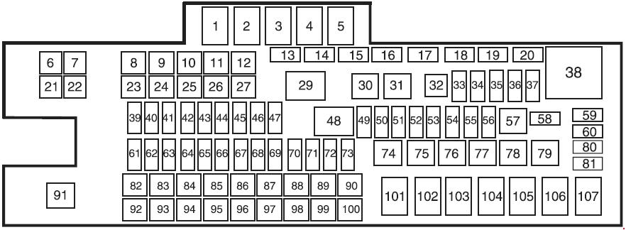
Engine Compartment Fuse Box
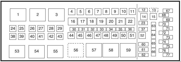
| Number | Ampere rating [A] | Description |
| 4 | — | — |
| 5 | 30 | Trailer Brake Controller (TBC) |
| 6 | 40 | ABS module (Pump) |
| 7 | 30 | Upfitter auxiliaiy switch #1 |
| 8 | 30 | Upfitter auxiliaiy switch #2 |
| 9 | 40 | ABS module (Coil) |
| 10 | 20 | Cigar lighter |
| 11 | 20 | Instrument panel power point |
| 12 | 15 | Brake On/Off (BOO) relay feed |
| 13 | 5 | Brake switch, Brake switch relay coil, SJB module, 4×4 module |
| 14 | — | — |
| 15 | — | — |
| 23 | 15 | Heater mirror, Heated spotted mirror |
| 24 | 40 | Blower motor relay |
| 25 | — | — |
| 26 | 30 | ESOF relay lo-hi |
| 27 | 50 | Diesel: Glow Plug Control Module (GPCM) #1 |
| 28 | 20 | Heated mirror relay |
| 29 | 30 | Passenger power seat |
| 30 | 10 | A/C dutch relay |
| 31 | 15 | Power fold mirror relay |
| 32 | 20 | Fuel pump relay |
| 33 | 20 | Back-up lamp relay |
| 34 | 25 | Trailer stop/turn relay |
| 35 | 5 | ESOF relay coils |
| 36 | 10 | Gasoline: Powertrain Control Module (PCM) keep alive power, Canister vent Diesel: Engine Control Module (ECM) keep alive power |
| 37 | 10 | Diesel: Transmission Control Module (TCM) |
| 38 | — | — |
| 39 | 50 | Diesel: ECM power |
| 40 | 30 | Starter relay |
| 41 | 20 | Power point (Center console -Front) |
| 42 | 30 | Trailer park lamp relay |
| 43 | 20 | Power point (Center console – Rear) |
| 44 | 30 | Trailer battery charge relay |
| 45 | 30 | Driver power seat or Memory module, Air ride seat |
| 46 | 40 | Run/Start relay |
| 47 | 50 | Diesel: GPCM #2 |
| 48 | 30 | ESOF relay lii-lo |
| 49 | 30 | Wiper motor |
| 50 | 30 | Gasoline: PCM relay coil, PCM relay |
| 51 | — | — |
| 52 | — | — |
| 63 | 15 | Trailer tow back-up lamps |
| 64 | 5 | Mirror marker lamps |
| 65 | — | — |
| 66 | — | — |
| 67 | — | — |
| 68 | — | — |
| 69 | — | — |
| 70 | 10 | Gasoline: A/C clutch relay coil, Refrigerant Containment Switch, Heated PCV Diesel: A/C clutch relay coil, Clutch switch, Fuel pump cooler, A/C cycle pressure switch |
| 71 | 5 | Fuel pump relay diode, PCM/E CM Run/Start power |
| 72 | 15 | Gasoline: Ignition coils |
| Diesel: Engine TCM | ||
| 73 | 2 | Reverse Camera System (RCS) |
| 74 | 20 | Gasoline: VPWR: Heated exhaust gas oxygen sensor, CMS, Mass air flow sensor, Electronic vapor management valve, CMCV, Variable cam timing, IMTV Diesel: VPWR: Engine loads |
| 75 | 5 | Back-up relay coil power |
| 76 | 20 | Gasoline: VPWR: PCM Diesel: VPWR: ECM |
| 77 | 10 | ABS module logic |
| Diode | ||
| 60 | Gasoline: Starter relay | |
| One-touch start (OTIS) | ||
| 61 | A/C clutch | |
| 62 | Fuel pump | |
| Relay | ||
| 1 | Blower motor/Variable blower control (Dual Zone Climate Control) | |
| 2 | Electronic Shift-on-the-Fly (ESOF) Lo-Hi | |
| 3 | Heater mirror | |
| 16 | A/C clutch | |
| 17 | Wipers | |
| 18 | Gasoline: Fuel Pump Driver Module (FPDM), Fuel injectors Diesel: Diesel Fuel Control Module (DFCM) |
|
| 19 | Back-up lamps, Reverse Sensing System (RSS), Engine compartment fuse 63 | |
| 20 | Trailer stop/turn (Left) | |
| 21 | Trailer stop/turn (Right) | |
| 22 | Stop lamps, Center High-Mounted Stop Lamp (CHMSL), TBC, Customer access | |
| 53 | Diesel: PCM power bus (Fuses 68, 70, 72, 74, 76) | |
| 54 | Starter solenoid | |
| 55 | Trailer tow park lamps | |
| 56 | Trailer tow battery charge | |
| 57 | Power Distribution Box (PDB) bus (fuses 67, 69, 71, 73, 75, 77) SJB Run /Start bus (Fuses 29-37, 46) |
|
| 58 | ESOF hi-lo | |
| 59 | Gasoline: PCM power bus (Fuses 68, 70, 72, 74, 76) | |
WARNING: Terminal and harness assignments for individual connectors will vary depending on vehicle equipment level, model, and market.